USD
USD
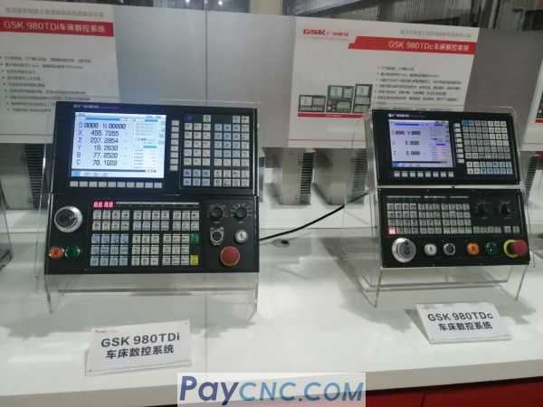
Alarm codes on GSK980TDc Controller
When there is alarm code shown on GSK980TDc CNC controller (or GSK980TDi, GSK980TDb, GSK980TD)
We can refer to below for the reason to trouble shoot.
We can refer to below for the reason to trouble shoot.
| Alarm No. | Content |
|---|---|
| 000 | Emergent stop alarm and ESP open circuit |
| 001 | There are no part programs or cannot open part programs |
| 002 | G command values are negative or with decimals |
| 003 | Characters are less than 2 or more than 11 for one word |
| 004 | Address error (address is A~Z) |
| 005 | Illegal command value |
| 006 | Block numbers are negative or with decimals |
| 007 | Illegal G commands |
| 008 | Execute G96 when the spindle analog voltage control is invalid |
| 009 | Command movement distance when G commands in 00 and 01 groups are not input and there are invalid commands in 01 group |
| 010 | There are the same addresses in one block |
| 011 | There are more than 20 words in one block |
| 012 | Command values exceed their valid range |
| 013 | Input S commands except for S00~S99 when the spindle analog voltage control is invalid |
| 014 | Input G commands in 00 and 01 groups in one block |
| 015 | Execute M commands for spindle automatic gear shifting when the spindle analog voltage control is invalid |
| 016 | Tool offset numbers exceed their valid range(0~32) |
| 017 | Tool number exceeds the range of No.084 parameter |
| 018 | The data specified by the interpolation command cannot form a correct curve, or there is no necessary command, or the data exceeds No.154 range |
| 019 | The tool group number exceeds the range ( 1~32 ) in the tool life management |
| 020 | Cannot execute T command in C tool nose radius compensation, cancel it |
| 024 | There is no G11 in the program |
| 025 | There is no tool in the current tool group in the tool life management |
| 026 | The current tool group has not been defined in the tool life management |
| 027 | The tool quantity exceeds 8 in the current tool group in tool life management |
| 028 | The tool life management function is invalid and G10 L3 cannot be used |
| 029 | G11 cannot be in front of G10 |
| 030 | X movement distance isn’t zero in G33 |
| 031 | G02 or G03 has changed monotony of corresponding coordinates in G71~G73 |
| 032 | Absolute value of R is more than that of U/2 in G90, G92 |
| 033 | Absolute value of R is more than that of W in G94 |
| 034 | There are more than 100 blocks in G70~G73 |
| 035 | Ns and Nf are reversed each other in G70~G73 |
| 036 | There is no Ns or Nf or they exceed their allowed range in G70~G73 |
| 037 | There is no Ns or Nf in G70~G73 |
| 038 | Single infeed exceeds its allowed range in G71 or G72 |
| 039 | Single tool retraction exceeds its allowed range in G71 or G72 |
| 040 | Total cutting travel exceeds its allowed range in G73 |
| 041 | Cycle times is less than 1 or more than 99999 in G73 |
| 042 | Single tool retraction R(e) exceeds its allowed range in G74 or G75 |
| 043 | The tool retraction is negative at the end of cutting in G74 or G75 |
| 044 | X/Z single cutting value exceeds its allowed range in G74 or G75 |
| 045 | Starting point of cutting taper thread is between thread starting point and its end point in G76 |
| 046 | Min. cutting value exceeds its allowed range in G76 |
| 047 | Finishing allowance exceeds its allowed range in G76 |
| 048 | Tooth height is less than finishing allowance or 0 in G76 |
| 049 | Cycle times exceeds its allowed range in G76 |
| 050 | Chamfer exceeds its allowed range in G76 |
| 051 | Angle of tool nose exceeds its allowed range in G76 |
| 052 | X/Z movement distance in G76 is zero |
| 053 | There is no specified tooth height P in G76 |
| 054 | There is no the first cutting depth Q or Q is 0 or Q is not input |
| 055 | Call subprograms in G70~G73 |
| 056 | Ns does not command G00 or G01 in G70~G73 |
| 057 | X value is not specified in the first block or the movement is 0 in G71 |
| 058 | Z value is not specified in the first block or the movement is 0 in G72 |
| 059 | Z value is not specified in G74 |
| 060 | Q value is 0 or is not input in G74 |
| 061 | X value is not specified in G75 |
| 062 | P value is 0 or is not input in G75 |
| 063 | Initial blocks are employed with the forbidden G commands in G70~G73 |
| 064 | End blocks are employed with the forbidden G commands in G70~G73 |
| 065 | Execute G70~G73 in MDI mode |
| 066 | The cycle starting point is in the closed area formed by the starting point and end point of the finishing path |
| 067 | Flute quantity is more than 10 |
| 068 | Parallel thread cutting path of cutting edge |
| 081 | Y cannot feed with X, Z |
| 082 | Have no the measured position arrival signal in parameter specifying area in automatic tool offset(G36,G37) |
| 083 | Specifying an invalid axis or a command is incremental in automatic tool offset(G36,G37). Modify the program |
| 084 | Have the measured position arrival signal in area set by the parameter in automatic tool offset(G36,G37) |
| 085 | The distance between the starting point and the target is less than the setting (142,143) in automatic tool offset(G36,G37), have no set the rapid motion area |
| 086 | The parameter (142,144) or (143,145) area setting are wrong in automatic tool offset(G36,G37) |
| 087 | Firstly create or set the coordinate system before executing G36,G37 |
| 088 | Firstly set the correct tool number and the compensation number before executingG36,G37 |
| 089 | The tool offset is in protection state, and cannot be written |
| 095 | Subprogram numbers are not input or are illegal when M98 calls them |
| 096 | Layers of nested subprograms are more than 4 |
| 097 | Calling programs in M98 is the current one(main program) |
| 098 | Use M98 or M99 in MDI mode |
| 099 | Use M98 or M99 in C tool radius compensation |
| 100 | Cannot use macro statement and macro command in C tool radius compensation |
| 101 | Operation values of H11, H12, H13, H25 are not binary in G65 |
| 102 | Operation value of H24 is more than 1023 in G65 |
| 103 | Denominator is 0 for division operation in G65 |
| 104 | G65 commands illegal H command |
| 105 | Macro variable number of G65 is illegal(error) |
| 106 | Macro variable P is not commanded or P value is zero in G65 |
| 107 | Variable Q is not commanded or Q value is zero when H commands except for H80 or H99 are commanded |
| 108 | Do not command variable R or R is illegal |
| 109 | P command value isn’t variable in G65 |
| 110 | Number with H21 in G65 is negative |
| 111 | H99 user alarm number in G65 exceeds its range |
| 112 | Block number of macro command (G65)skip or M99 program return exceeds their range |
| 113 | There is no block number for block skip or M99 program return |
| 114 | G65, G66 command format are mistaken |
| 115 | G65 H_operand is mistaken |
| 120 | The thread graduation heads are more than 65535 |
| 121 | The spindle encode lines are not in 100–5000 |
| 130 | Programmed axis name is invalid |
| 131 | G31G32G32.1G33G34G46G47G84G88Y cannot be used to C tool nose radius compensation |
| 132 | Y has no chamfer function |
| 133 | Skip in G65 or the block number of M99 return does not exist |
| 134 | Cannot specify the cylinder radius again |
| 135 | The linear or rotary axis setting used to the cylinder interpolation is mistaken |
| 136 | Only currently use the tool nose direction T0 or T9 to create C tool compensation |
| 140 | The marco format is specified in error |
| 141 | DO,END tabs are not 1,2,3 in macro statement |
| 142 | DO,END formats are specified in error |
| 143 | The brackets are not matched in macro statement or the format is specified in error |
| 144 | The divisor in macro statement cannot be 0 |
| 145 | The specified anti-tangent ATAN format is mistaken in macro statement |
| 146 | The anti logarithm of LN in macro statement is 0 or less than 0 |
| 147 | The square root in macro statement cannot be negative |
| 148 | The tangent TAN result in macro statement is endless |
| 149 | The operands of anti sine or anti cosine in macro statement exceed the range between -1 and 1 |
| 150 | The macro variable number or the variable value is illegal(error) in marco statement |
| 151 | The local variable is empty |
| 152 | The variable #0 is always empty and cannot be operated |
| 153 | The operand in marco statement is not binary |
| 232 | Specify the axis movement command in M29 or G84/G88 |
| 233 | The rigid tapping specifies the tool nose radius compensation |
| 234 | Specify M29 repetitively or not input M29 before rigid tapping |
| 235 | The spindle must be oriented, M29 cannot be with G84/G88 in the same block when rigid tapping |
| 236 | Set the axis used to the spindle control to the rotary axis before the rigid tapping/rigid thread machining |
| 238 | Have not selected the spindle used to the rigid tapping for the multi-spindle function device when rigid tapping |
| 239 | Cannot switch the spindle used to the tapping when rigid tapping |
| 251 | Mistake in programming causes an error of C tool nose radius compensation |
| 252 | Mistake in programming causes an end point of arc machining is not on the arc in the course of C tool nose radius compensation |
| 253 | Mistake in programming causes there are the same coordinates for two neighbouring points not to execute C tool nose radius compensation |
| 254 | Mistake in programming causes there are the same coordinates between center point and starting point of arc not to execute C tool nose radius compensation |
| 255 | Mistake in programming causes there are the same coordinates between center point and end point of arc not to execute C tool nose radius compensation |
| 256 | Arc radius is less than that of tool nose to cause not to execute C tool nose radius compensation |
| 257 | Mistake in programming causes there is not intersection of two arcs of current tool radius in the course of C tool nose radius compensation |
| 258 | Specify one arc command as executing C tool nose radius compensation |
| 259 | Specify one arc command as canceling C tool nose radius compensation |
| 260 | There is excessive cutting as checking C tool nose radius compensation |
| 261 | Mistake in programming causes there is not intersection between straight line and arc of current tool radius in the course of C tool nose radius compensation |
| 262 | Mistake in programming causes there is not intersection between arc and straight line of current tool radius in the course of C tool nose radius compensation |
| 263 | There are too non movement commands in C too radius compensation, the buffer overflows |
| 281 | The linear chamfer length is too length |
| 282 | The arc chamfer radius is too big |
| 283 | The linear chamfer leanth is too big or the arc data is mistaken |
| 284 | The arc chamfer radius is too big or the arc data is mistaken |
| 285 | The linear chamfer length is too big or the arc data is mistaken |
| 286 | The arc chamfer radius is too big or the arc data is mistaken |
| 287 | The linear chamfer length is too big or the intersection is not on the arc |
| 288 | The arc chamfer radius is too big or the intersection is not on the arc |
| 289 | The chamfer cannot be executed in end position |
| 290 | Cannot start the polar coordinate and the cylinder interpolation in C tool compensation state or G99 |
| 291 | The linear axis or rotary axis of the polar coordinates does not correspond to No.189 or No.191 or No.193 or the linear axis attribution setting is mistaken |
| 292 | Execute the length compensation of all axes before starting the polar coordinates |
| 293 | X cannot be negative or 0 in G16/G15 |
| 294 | Have used the command which cannot be used to the polar coordinates and the cylinder interpolation |
| 295 | C tool compensation is not cancelled in the polar coordinates and the cylinder interpolation |
| 301 | Parameter switch has been on |
| 302 | CNC initialization is failure |
| 303 | Cannot open part programs |
| 304 | Fail to save part programs |
| 305 | Total lines of part program exceed its range (69993) |
| 306 | Illegal dictates have been input |
| 307 | Memory capacity is not enough |
| 308 | Program numbers exceed the range |
| 309 | Editing macro program is forbidden under its current operation authority |
| 310 | Cannot open PLC programs (ladder) |
| 311 | Edit software version of PLC programs (ladder) is inconsistent |
| 312 | First-grade PLC program is too long |
| 313 | The edit keyboard or operator panel is failure |
| 314 | The memorizer is failure, check it or power on again |
| 315 | Electronic gear ratio setting is mistaken |
| 316 | Set the rotary axis function be to valid before using CS axis or rigid tapping |
| 317 | CS axis position is mistaken(must not switch the spindle working mode when CS axis is working) |
| 318 | Cannot move CS axis when the spindle is not switched to the position control mode |
| 320 | CPU voltage is abnormal. Please check the power supply and restart |
| 324 | There is only basic axis XYZ |
| 325 | Cannot set simultaneously two or more CS axis to be valid when the multi-spindle control function is invalid or the 2nd CS function is not started |
| 326 | Y axis cannot set to CS controllable axis when the multi-spindle control function is valid and the 2nd CS function is valid |
| 330 | The axis name of additional axis is not in the setting range or, the axis names of two or more than two additional are the same ones, please set again data parameter#225~#227 |
| 340 | USB read/write file is mistaken( connect with the device again) |
| 341 | The system has been upgraded and updated, and is valid after power-on again |
| 354 | The system parameter is modified, and is turned on again |
| 356 | Modifying the ladder is successful, please turn on the CNC again |
| 361 | The least incremental system setting of additional axis(Y,4th,5th) cannot be less than the least incremental system (IS-B,IS-C)of the current system, please set it again |
| 354 | The system parameter is modified, and is turned on again |
| 356 | Modifying ladder is successful, turn on the CNC again |
| 361 | Least increment system setting of additional axis (Y, 4th, 5th axis) must not be less than that of the current system (IS-B, IS-C), please set it again |
| 401 | The program reference point is not specified Troubleshooting Press reset to clear alarm, set program zero in G50 |
| 402 | Max. spindle speed at some gear is not specified and check No.037~No.040 |
| 403 | Run speed is too rapid |
| 404 | Feedrate is cancelled owing to spindle stopping |
| 405 | Spindle speed is too low when machining thread |
| 406 | Spindle speed is too high when machining thread Troubleshooting Press reset to clear the alarm, check the spindle and modify NO.106 |
| 407 | Fluctuation of spindle speed is excessive when machining thread |
| 408 | Pitch is less than 0 when the variable pitch is machined |
| 409 | The reference point is not created, and 2nd, 3rd, 4th reference point return cannot be executed |
| 410 | Zero return mode A, zero return failure |
| 411 | Exceeding X axis positive software travel limit |
| 412 | Exceeding Z axis positive software travel limit |
| 413 | Exceeding Y axis positive software travel limit |
| 414 | Exceeding the 4th axis software travel limit |
| 415 | Exceeding the 5th axis software travel limit |
| 416 | Exceeding X negative software travel limit Troubleshooting Press reset to clear the alarm, negatively move X |
| 417 | Exceeding Z negative software travel limit Troubleshooting Press reset to clear the alarm, positively move X |
| 418 | Exceeding Y negative software travel limit Troubleshooting Press reset to clear the alarm, negatively move Z |
| 419 | Exceeding 4th negative software travel limit Troubleshooting Press reset to clear the alarm, positively move X |
| 420 | Exceeding 5th negative software travel limit |
| 421 | X drive unit is not ready |
| 422 | Z drive unit is not ready |
| 423 | Y positive overtravel |
| 424 | 4th positive overtravel |
| 425 | 5th positive overtravel |
| 426 | X negative overtravel |
| 427 | Z negative overtravel |
| 428 | Y negative overtravel |
| 429 | 4th negative overtravel |
| 430 | 5th negative overtravel |
| 431 | X drive unit have not been ready |
| 432 | Z drive unit have not been ready |
| 433 | Y drive unit have not been ready |
| 434 | 4th drive unit have not been ready |
| 435 | 5th drive unit have not been ready |
| 437 | PLC axis is working and cannot be switched |
| 438 | CNC axis is working and cannot be switched |
| 439 | PLC axis is working and cannot be operated |
| 440 | CNC emergent stop is failure(restart the CNC) |
| 450 | Data is error! Start the system again to return the machine zero, execute the toolsetting again to check all parameters |
| 491 | CNC system document identifier error (Contact with us) |
| 492 | CNC system document identifier error (Contact with us) |
Operation Prompt
All prompts will be displayed in “PROMPT LINE” in bottom left corner of display interface.
| Content | Prompting operation |
|---|---|
| Memory full | Program number exceeds 384 or total memory capacity exceeds 6144KB |
| Error data | Input data is out of range |
| Block exceeding | Input block exceeds 255 characters |
| Unallowed input | Input data includes unrecognizable characters |
| Serial interface not connected | Doing communication under unconnected serial interface |
| Communication error | Error data transferring |
| Fail to delete blocks | Not find object characters during deleting blocks |
| Fail to search | Not find object characters in cursor searching up or down |
| Row exceeding | Limit to the max. lines (69993) of part programs and forbid to add lines |
| Illegal G | Illegal dictates have been input |
| File not existed | Not search object part program |
| File existed | There is the same file when saving as or renaming a program |
| Modify in parameter page | When modifying parameters in diagnosis page |
| Mistaken operation mode | Open a program or press [OUT] to execute the data transmission in file window |
| File deleted | The target part program has been deleted when deleting part programs |
PLC Alarm (standard PLC ladder definition)
| No. | Content | Address |
|---|---|---|
| 1000 | Tool change time is too long | A0000.0 |
| 1001 | Alarm of toolpost not in-position at the end of tool change | A0000.1 |
| 1002 | Alarm of tool change not finished | A0000.2 |
| 1003 | Can’t execute M10 and M11 under invalid tailstock function | A0000.3 |
| 1004 | Can’t retreating tailstock when spindle rotating | A0000.4 |
| 1005 | The tool change execution error when power off | A0000.5 |
| 1006 | Can’t start cycle when cycle start enabling is closed | A0000.6 |
| 1007 | Can’t start the spindle when thespindle start enabling is closed | A0000.7 |
| 1008 | Tailstock function is invalid, M10 and M11 cannot be executed | A0001.0 |
| 1009 | The thread run-out cannot be executed in spindle rotating | A0001.1 |
| 1011 | Have not checked the tailstock forward and cannot start the spindle | A0001.3 |
| 1012 | Tool change mode A and B can have up to 8 tools | A0001.4 |
| 1015 | Confirm the tool quantity of the tool post (6,8,10,12) | A0001.7 |
| 1016 | Alarm of protection door not closed | A0002.0 |
| 1017 | Chuck low pressure alarm | A0002.1 |
| 1019 | Can’t unclamp chuck when spindle rotating | A0002.3 |
| 1020 | Alarm of invalid clamping in-position signal when spindle rotating | A0002.4 |
| 1021 | Can’t start spindle when clamping in-position signal | A0002.5 |
| 1022 | Can’t start spindle when chuck is unclamped | A0002.6 |
| 1024 | Can’t execute M12 or M13 under invalid chuck function | A0003.0 |
| 1025 | Have not checked chuck clamping/releasing in-position signal | A0003.1 |
| 1027 | The tool pot is not released | |
| 1028 | Has not found the target tool | |
| 1029 | Has not received tool pot stop and locking start signal | |
| 1031 | Total tools is more than 4, and the external override cannot be connected | |
| 1032 | Illegal M code | A0004.0 |
| 1033 | Spindle jogging function is invalid under invalid analog spindle | A0004.1 |
| 1034 | Setting error for M03 and M04 | A0004.2 |
| 1035 | M63, M64 designation error | |
| 1036 | Spindle gear change time is too long | |
| 1037 | Spindle speed/position control switch time is too long | A0004.5 |
| 1038 | The 2nd spindle speed/position control switch time is too long | |
| 1039 | Spindle position control does not permit the orientation | |
| 1040 | Spindle orientation time is too long | |
| 1041 | Alarm for the abnormal spindle servo or frequency converter for abnormality | |
| 1042 | Alarm for the abnormal 2nd spindle servo or frequency converter | |
| 1043 | Forbid clamping the spindle when the spindle rotating or feeding | |
| 1044 | Spindle is clamped not to rotate or feed | |
| 2000 | Hydraulic motor is not started | |
| 2001 | Safety door has been opened | |
| 2003 | Alarm for the tool pot unclocked |