USD
USD
Ball screw installation and gap adjustment method
Ball screw installation and gap adjustment method
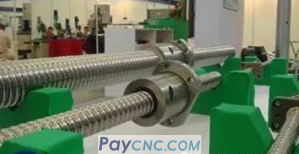
The ball screw pair is a spiral transmission element that uses balls as rolling elements between the screw and the nut. It is an advanced transmission element with precision, high efficiency, high rigidity, long life, and energy saving. It can rotate the motor The movement is transformed into the linear movement of the worktable, so it is widely used in machine manufacturing, especially CNC machine tools and machining centers, which provides good conditions for the high efficiency and high speed of the host.
With the ever-increasing requirements for the accuracy of CNC machine tools and machining centers, the high-precision of the ball screw pair has become an inevitable trend of development, and the installation accuracy on the host has gradually become a prominent problem in assembly. In order to achieve the accuracy of the coordinate position of the machine tool It is required to reduce the winding degree of the screw, prevent radial and offset loads, reduce the heating and thermal deformation of each link of the screw shaft system, reduce the transmission torque of the servo motor to the greatest extent and improve the reliability of the continuous operation of the machine tool. The installation accuracy of the ball screw pair on the machine tool.
The commonly used installation methods of ball screw pairs are usually as follows: double push-free method; double push-support method; double push-double push method.
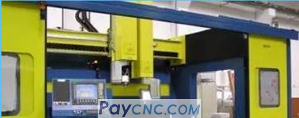
The large horizontal machining center is a high-performance, high-rigidity and high-precision mechatronics high-efficiency machining equipment. It is an ideal machining equipment for processing various high-precision transmission box parts and other large molds. Its three coordinate directions are all driven by a servo motor to drive a rolling screw drive, and the three coordinate directions, namely X, Y, and Z, have a relatively large working stroke.
Due to the structural characteristics of the ball screw pair, the installation of the ball screw pair in three directions on the main machine becomes particularly critical.
According to the traditional process method, the installation of the ball screw always uses a mandrel and a positioning sleeve to connect the two ends supporting bearing seat and the middle nut seat together for correction, and use a dial indicator to align the mandrel axis and the machine tool guide rail in parallel and make the core The rod can be driven freely and briskly.
This installation method is more convenient to apply to small CNC machine tools and machining centers with small strokes in the three coordinate directions.
Due to the matching gap between the core rod and the positioning sleeve, the positioning sleeve and the bearing holes supported at both ends, and the nut housing hole in the middle, the coaxiality error of the supporting bearing hole and the nut housing hole after installation is often large, resulting in A series of serious consequences such as the increase of the screw winding degree, the increase of the radial offset load, the temperature increase of each link of the screw shaft system, the increase of thermal deformation and the increase of the transmission torque, which cause the servo motor to overload and overheat, and the servo system alarms , Affecting the normal operation of the machine tool.
In addition, the actual difference between the bearing holes at both ends and the middle nut housing hole cannot be accurately measured, which affects further precise adjustments. For CNC machine tools and machining centers with large strokes in the three coordinate directions, since the mandrel required is more than 1500mm, the machining is difficult and the accuracy is not easy to ensure, so the alignment method of the mandrel and the positioning sleeve cannot be used for the ball screw pair. installation.
In the production of a certain type of horizontal machining center, because the three coordinate strokes of the machine tool are relatively large, in the process of installation using traditional technology, the coaxiality of the bearing holes at both ends and the center screw socket hole is out of tolerance, resulting in a ball screw Increased radial and offset loads, frequent servo motor overload, overheating, servo system alarms, etc., make the machine tool unable to run continuously, and seriously affect the service life and transmission accuracy of the ball screw, and shorten the maintenance cycle of the host.
Utilize other assembly methods, such as the use of movable sliding saddles to shorten the distance between the nut holder and the bearing holder, and the method of aligning the nut holder and the bearing holders at both ends separately. Since two sections are required to be aligned separately, plus inspection rod and inspection The fitting clearance of the sleeve is not ideal in actual application, and the above-mentioned problems also exist.
Through the on-site technical research of this product, after repeated exploration and production verification, a relatively reliable assembly process method was summed up.

First of all, use the integral special mandrel to correct the nut holder hole so that the parallelism between the front and the side of the reference guide rail is within 0.01/1000; after fixing the nut holder, use a professional measuring fixture to actually measure the nut holder The positive and lateral distance between the hole and the reference guide rail; then, use the integral special inspection rod to find the positive and lateral parallelism of the bearing hole and the reference guide rail within 0.01/1000, and use the special measuring fixture to actually measure the bearing hole distance The positive and lateral distances of the reference guide rail require the same distance between the nut hole and the reference guide rail, with a tolerance of 0.01; fix the bearing seat. This method uses an integrated special inspection rod, which is not only short in length, but also combines the core rod and the positioning sleeve into one, which eliminates the matching gap between the core rod and the positioning sleeve, and reliably ensures that the bearing hole, nut seat hole and Parallelism of the guide rail; through the actual distance measurement, the coaxiality of the bearing support holes at both ends and the nut seat hole is also reliably guaranteed, which reduces the winding and radial offset load of the ball screw pair , Improve the installation accuracy of the screw pair.
In addition, in the process of installing the ball screw, the axial movement of the ball screw must be strictly controlled. This technical index will directly affect the transmission position accuracy of the ball screw support seat feed system.
According to the actual verification on site, firstly, the bearing in the bearing seat of the servo motor should be assembled. It plays a major role in the transmission process of the rolling screw, and the axial movement of the ball screw is controlled between 0.015 and 0.02. ;

Then, assemble the bearing in the bearing seat at the other end to control the axial movement within 0.01. In this way, the rigidity and accuracy of the ball screw feed system can be effectively guaranteed.
The pre-tensioning of the ball screw shaft is also very necessary.
In order to improve the rigidity and accuracy of the ball screw feed system, it is very effective to pre-stretch the screw shaft. However, due to the different sections of the screw shaft and the temperature rise value is not easy to accurately set, it is calculated according to the relevant literature. The obtained pre-tension can only be used as a reference value.
In production, the lead screw shaft with the target value in the negative direction is often pre-stretched to make the positioning accuracy curve of the machine tool table close to the level.
In production, the no-load torque of the ball screws in the three coordinate directions of a large machining center assembled by the above-mentioned new process method is significantly reduced, the no-load current is also significantly reduced, and the servo motor and servo system work normally. Servo alarms in three coordinate directions appear, and the machine tool can run continuously for more than 72 hours.
The above results fully show that the new process method can effectively ensure the installation accuracy of the ball screw pair. In addition, the method is not limited by the stroke size of the machine tool. The greater the stroke of the machine tool, the more it can highlight its advantages, which provides an effective and reliable method for the installation of ball screw pairs of large-scale CNC machine tools and machining centers.
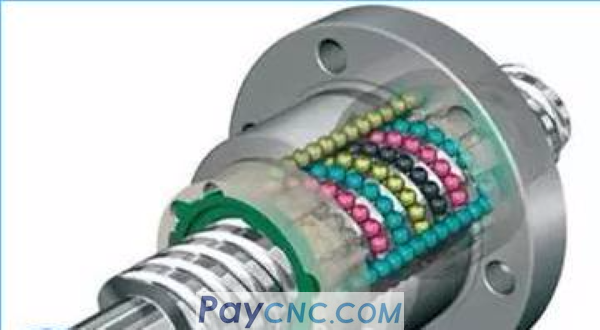
There are mainly three methods to adjust the gap of the ball screw:
1. Gasket adjustment type:
Screws are usually used to connect the flanges of the two nuts of the ball screw, and a gasket is added between the flanges. Adjust the thickness of the washer to make the nut produce axial displacement to achieve the purpose of eliminating the gap and generating pre-tensioning force. The characteristics of this structure are simple structure, good reliability, high rigidity and convenient loading and unloading. However, the adjustment is time-consuming and cannot be adjusted at will during work unless the gasket with a different thickness is replaced.
2. Thread adjustment type:
One of the nuts has a flange at the outer end and the other nut has no flange at the outer end and is threaded. It protrudes out of the sleeve and is fixed by two round nuts. When the round nut is rotated, the gap can be eliminated and a pre-tensioning force is generated. After adjustment, another round nut can be used to lock it.
3. Tooth gap adjustment type:
Cylindrical gears are respectively made on the flanges of the two nuts, the number of teeth of the two differs by one tooth, and they are installed in the inner gear ring, which is fixed on the sleeve with screws or positioning pins. When adjusting, first remove the inner gear ring at both ends. When the two ball nuts rotate the same number of teeth in the same direction with respect to the sleeve, one ball nut produces a relative angular displacement to the other ball nut, so that the ball nut has a relative angular displacement to the ball screw. The raceways move relatively to eliminate the gap and apply pre-tightening force.
The ball screw pair is a spiral transmission element that uses balls as rolling elements between the screw and the nut. It is an advanced transmission element with precision, high efficiency, high rigidity, long life, and energy saving. It can rotate the motor The movement is transformed into the linear movement of the worktable, so it is widely used in machine manufacturing, especially CNC machine tools and machining centers, which provides good conditions for the high efficiency and high speed of the host.
With the ever-increasing requirements for the accuracy of CNC machine tools and machining centers, the high-precision of the ball screw pair has become an inevitable trend of development, and the installation accuracy on the host has gradually become a prominent problem in assembly. In order to achieve the accuracy of the coordinate position of the machine tool It is required to reduce the winding degree of the screw, prevent radial and offset loads, reduce the heating and thermal deformation of each link of the screw shaft system, reduce the transmission torque of the servo motor to the greatest extent and improve the reliability of the continuous operation of the machine tool. The installation accuracy of the ball screw pair on the machine tool.
The commonly used installation methods of ball screw pairs are usually as follows: double push-free method; double push-support method; double push-double push method.
The large horizontal machining center is a high-performance, high-rigidity and high-precision mechatronics high-efficiency machining equipment. It is an ideal machining equipment for processing various high-precision transmission box parts and other large molds. Its three coordinate directions are all driven by a servo motor to drive a rolling screw drive, and the three coordinate directions, namely X, Y, and Z, have a relatively large working stroke.
Due to the structural characteristics of the ball screw pair, the installation of the ball screw pair in three directions on the main machine becomes particularly critical.
According to the traditional process method, the installation of the ball screw always uses a mandrel and a positioning sleeve to connect the two ends supporting bearing seat and the middle nut seat together for correction, and use a dial indicator to align the mandrel axis and the machine tool guide rail in parallel and make the core The rod can be driven freely and briskly.
This installation method is more convenient to apply to small CNC machine tools and machining centers with small strokes in the three coordinate directions.
Due to the matching gap between the core rod and the positioning sleeve, the positioning sleeve and the bearing holes supported at both ends, and the nut housing hole in the middle, the coaxiality error of the supporting bearing hole and the nut housing hole after installation is often large, resulting in A series of serious consequences such as the increase of the screw winding degree, the increase of the radial offset load, the temperature increase of each link of the screw shaft system, the increase of thermal deformation and the increase of the transmission torque, which cause the servo motor to overload and overheat, and the servo system alarms , Affecting the normal operation of the machine tool.
In addition, the actual difference between the bearing holes at both ends and the middle nut housing hole cannot be accurately measured, which affects further precise adjustments. For CNC machine tools and machining centers with large strokes in the three coordinate directions, since the mandrel required is more than 1500mm, the machining is difficult and the accuracy is not easy to ensure, so the alignment method of the mandrel and the positioning sleeve cannot be used for the ball screw pair. installation.
In the production of a certain type of horizontal machining center, because the three coordinate strokes of the machine tool are relatively large, in the process of installation using traditional technology, the coaxiality of the bearing holes at both ends and the center screw socket hole is out of tolerance, resulting in a ball screw Increased radial and offset loads, frequent servo motor overload, overheating, servo system alarms, etc., make the machine tool unable to run continuously, and seriously affect the service life and transmission accuracy of the ball screw, and shorten the maintenance cycle of the host.
Utilize other assembly methods, such as the use of movable sliding saddles to shorten the distance between the nut holder and the bearing holder, and the method of aligning the nut holder and the bearing holders at both ends separately. Since two sections are required to be aligned separately, plus inspection rod and inspection The fitting clearance of the sleeve is not ideal in actual application, and the above-mentioned problems also exist.
Through the on-site technical research of this product, after repeated exploration and production verification, a relatively reliable assembly process method was summed up.
First of all, use the integral special mandrel to correct the nut holder hole so that the parallelism between the front and the side of the reference guide rail is within 0.01/1000; after fixing the nut holder, use a professional measuring fixture to actually measure the nut holder The positive and lateral distance between the hole and the reference guide rail; then, use the integral special inspection rod to find the positive and lateral parallelism of the bearing hole and the reference guide rail within 0.01/1000, and use the special measuring fixture to actually measure the bearing hole distance The positive and lateral distances of the reference guide rail require the same distance between the nut hole and the reference guide rail, with a tolerance of 0.01; fix the bearing seat. This method uses an integrated special inspection rod, which is not only short in length, but also combines the core rod and the positioning sleeve into one, which eliminates the matching gap between the core rod and the positioning sleeve, and reliably ensures that the bearing hole, nut seat hole and Parallelism of the guide rail; through the actual distance measurement, the coaxiality of the bearing support holes at both ends and the nut seat hole is also reliably guaranteed, which reduces the winding and radial offset load of the ball screw pair , Improve the installation accuracy of the screw pair.
In addition, in the process of installing the ball screw, the axial movement of the ball screw must be strictly controlled. This technical index will directly affect the transmission position accuracy of the ball screw support seat feed system.
According to the actual verification on site, firstly, the bearing in the bearing seat of the servo motor should be assembled. It plays a major role in the transmission process of the rolling screw, and the axial movement of the ball screw is controlled between 0.015 and 0.02. ;
Then, assemble the bearing in the bearing seat at the other end to control the axial movement within 0.01. In this way, the rigidity and accuracy of the ball screw feed system can be effectively guaranteed.
The pre-tensioning of the ball screw shaft is also very necessary.
In order to improve the rigidity and accuracy of the ball screw feed system, it is very effective to pre-stretch the screw shaft. However, due to the different sections of the screw shaft and the temperature rise value is not easy to accurately set, it is calculated according to the relevant literature. The obtained pre-tension can only be used as a reference value.
In production, the lead screw shaft with the target value in the negative direction is often pre-stretched to make the positioning accuracy curve of the machine tool table close to the level.
In production, the no-load torque of the ball screws in the three coordinate directions of a large machining center assembled by the above-mentioned new process method is significantly reduced, the no-load current is also significantly reduced, and the servo motor and servo system work normally. Servo alarms in three coordinate directions appear, and the machine tool can run continuously for more than 72 hours.
The above results fully show that the new process method can effectively ensure the installation accuracy of the ball screw pair. In addition, the method is not limited by the stroke size of the machine tool. The greater the stroke of the machine tool, the more it can highlight its advantages, which provides an effective and reliable method for the installation of ball screw pairs of large-scale CNC machine tools and machining centers.
There are mainly three methods to adjust the gap of the ball screw:
1. Gasket adjustment type:
Screws are usually used to connect the flanges of the two nuts of the ball screw, and a gasket is added between the flanges. Adjust the thickness of the washer to make the nut produce axial displacement to achieve the purpose of eliminating the gap and generating pre-tensioning force. The characteristics of this structure are simple structure, good reliability, high rigidity and convenient loading and unloading. However, the adjustment is time-consuming and cannot be adjusted at will during work unless the gasket with a different thickness is replaced.
2. Thread adjustment type:
One of the nuts has a flange at the outer end and the other nut has no flange at the outer end and is threaded. It protrudes out of the sleeve and is fixed by two round nuts. When the round nut is rotated, the gap can be eliminated and a pre-tensioning force is generated. After adjustment, another round nut can be used to lock it.
3. Tooth gap adjustment type:
Cylindrical gears are respectively made on the flanges of the two nuts, the number of teeth of the two differs by one tooth, and they are installed in the inner gear ring, which is fixed on the sleeve with screws or positioning pins. When adjusting, first remove the inner gear ring at both ends. When the two ball nuts rotate the same number of teeth in the same direction with respect to the sleeve, one ball nut produces a relative angular displacement to the other ball nut, so that the ball nut has a relative angular displacement to the ball screw. The raceways move relatively to eliminate the gap and apply pre-tightening force.