USD
USD
CNC G Codes Learning
The programming technology of CNC machining center has always been the core part of CNC machine tools. How to write the program instructions accurately plays an extremely important role in the operation and precise operation of the lathe. It tells the machine how to perform the operation and accomplish the purpose of the cutting machine. Let's take a look at the various commands commonly used in CNC turning~
1. Quick point positioning command (G00)
This command can make the tool post move quickly from the current point of the tool post to the target point in the point position control mode at the fastest speed set by the machine tool factory. This command does not need to specify the feed speed~
G00 instruction format:
G00 X_Z_, or G00 U_W_
Program as shown below:
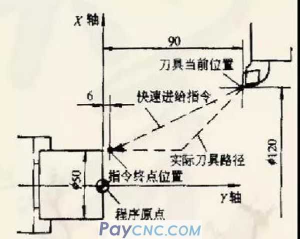
Starting point coordinates (120,90)
End point coordinates (50,6)
The program for fast reading from the start point to the end point is: G00 X50, Z6 or
G00 U70 W8
2. Linear interpolation command G01
This instruction is used to move the tool post linearly or obliquely from the current point to the target point at a given feed rate, that is, the tool post moves linearly along the X-axis or Z-axis direction, or it can move in the X-axis direction in a two-axis linkage mode. , Make a linear motion with any slope in the Z axis.
Instruction format:
G01 X_Z_F_ or G01 U_W_F_
G01 instruction parameters:
X, Z: absolute coordinates of the cutting end point;
U, W: the relative coordinates of the cutting end point relative to the starting point;
F: Feed rate, if the feed rate F value is repeatedly given in the previous program and does not need to be changed, this program can also not be written;
If a weak axis has no feed, then the axis command can be omitted in the command.
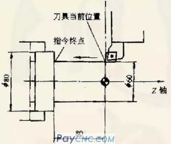
[Example] Outer cylindrical cutting programming
program:
G01 X60.0 Z-80.0 F0.4 or G01 U0.0 W-80.0 F0.4
Since the X coordinate of the start point and end point has not changed, it can also be:
G01 W80.0 F0.4 or G01 Z-80.0 F0.4
3. Circular interpolation command (G02, G03)
This command is used for the tool post to make a circular motion to cut out the arc contour. G02 is for the tool post to perform circular interpolation in the clockwise direction, and G03 is for the counterclockwise circular interpolation.
Instruction format:
G02 X_Z_R_F or G02 X_Z_l_K _F
G03 X_Z_R_F or G02 X_Z_l_K _F
Instruction parameters:
X, Z: arc end point coordinates
R: arc radius
I
K
F: Feed speed
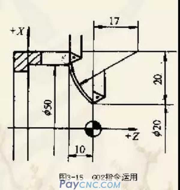
[Example] Clockwise circular interpolation
As shown in the figure:
Use (I, K) instructions:
G02 X50.0 Z-10.0 120. K17. F0.4 or
G02 U30.0 W-10.0 120. K17. F0.4
Use (R) command:
G02 X50.0 Z-10.0 R27.0 F0.4 or
G02 U30.0 W-10.0 R27.0 F0.4
4. Thread cutting command (G32)
This command is used to cut cylindrical threads, tapered threads and face threads.
Instruction format:
G32 X_Z_F_
Where F is the pitch of the thread
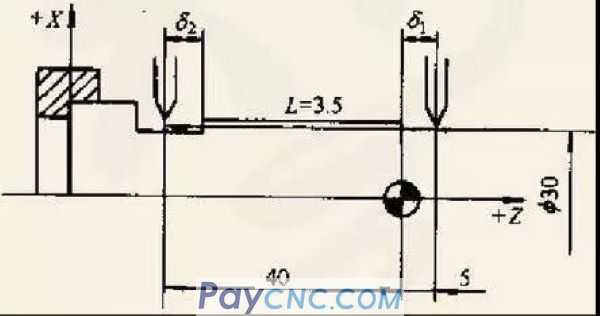
[Example] Cylindrical thread cutting
As shown below:
Thread cutting starting point &1: generally take an integer multiple of the pitch
Thread withdrawal amount&2: one to two times the pitch
G32 Z-40.0 F2.5 or G32 W-45 F2.5
5. Pause instruction (G04)
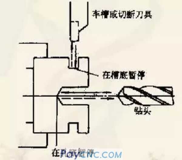
This command can make the props stop for a short time (N seconds) to perform feed smoothing processing. It is mainly used for cutting ring grooves, non-through holes and automatic thread processing, as shown in the figure below.
Instruction format:
G04 P_
Where P is followed by the dwell time, in seconds.
1. Quick point positioning command (G00)
This command can make the tool post move quickly from the current point of the tool post to the target point in the point position control mode at the fastest speed set by the machine tool factory. This command does not need to specify the feed speed~
G00 instruction format:
G00 X_Z_, or G00 U_W_
Program as shown below:
Starting point coordinates (120,90)
End point coordinates (50,6)
The program for fast reading from the start point to the end point is: G00 X50, Z6 or
G00 U70 W8
2. Linear interpolation command G01
This instruction is used to move the tool post linearly or obliquely from the current point to the target point at a given feed rate, that is, the tool post moves linearly along the X-axis or Z-axis direction, or it can move in the X-axis direction in a two-axis linkage mode. , Make a linear motion with any slope in the Z axis.
Instruction format:
G01 X_Z_F_ or G01 U_W_F_
G01 instruction parameters:
X, Z: absolute coordinates of the cutting end point;
U, W: the relative coordinates of the cutting end point relative to the starting point;
F: Feed rate, if the feed rate F value is repeatedly given in the previous program and does not need to be changed, this program can also not be written;
If a weak axis has no feed, then the axis command can be omitted in the command.
[Example] Outer cylindrical cutting programming
program:
G01 X60.0 Z-80.0 F0.4 or G01 U0.0 W-80.0 F0.4
Since the X coordinate of the start point and end point has not changed, it can also be:
G01 W80.0 F0.4 or G01 Z-80.0 F0.4
3. Circular interpolation command (G02, G03)
This command is used for the tool post to make a circular motion to cut out the arc contour. G02 is for the tool post to perform circular interpolation in the clockwise direction, and G03 is for the counterclockwise circular interpolation.
Instruction format:
G02 X_Z_R_F or G02 X_Z_l_K _F
G03 X_Z_R_F or G02 X_Z_l_K _F
Instruction parameters:
X, Z: arc end point coordinates
R: arc radius
I
K
F: Feed speed
[Example] Clockwise circular interpolation
As shown in the figure:
Use (I, K) instructions:
G02 X50.0 Z-10.0 120. K17. F0.4 or
G02 U30.0 W-10.0 120. K17. F0.4
Use (R) command:
G02 X50.0 Z-10.0 R27.0 F0.4 or
G02 U30.0 W-10.0 R27.0 F0.4
4. Thread cutting command (G32)
This command is used to cut cylindrical threads, tapered threads and face threads.
Instruction format:
G32 X_Z_F_
Where F is the pitch of the thread
[Example] Cylindrical thread cutting
As shown below:
Thread cutting starting point &1: generally take an integer multiple of the pitch
Thread withdrawal amount&2: one to two times the pitch
G32 Z-40.0 F2.5 or G32 W-45 F2.5
5. Pause instruction (G04)
This command can make the props stop for a short time (N seconds) to perform feed smoothing processing. It is mainly used for cutting ring grooves, non-through holes and automatic thread processing, as shown in the figure below.
Instruction format:
G04 P_
Where P is followed by the dwell time, in seconds.