USD
USD
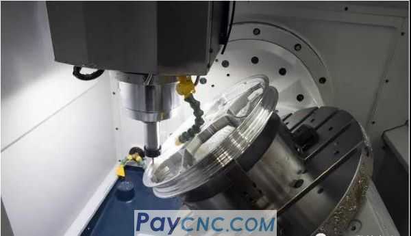
CNC program examples about spindle and sub spindle
1. The workpiece is cut off in the main shaft and transferred to the sub-spindle
If the main and counter axis phase synchronization is required, insert a section (M07) separately below the M32 block in the following program
N____; sequence number and additional information in parentheses
G10 P0 Z-____; input work offset from the program
G97 S____M14 P1; set spindle speed and direction
M98 P1; call safety subroutine
T____; designated tool position and tool compensation
X____Z____M32;Quickly move to the starting point, the main and auxiliary axes are synchronized
G50 S____; limit the maximum speed of the sub-spindle
G96 S____; set surface speed
M56; sub-spindle chuck loosened
G0 E____; rapid positioning of the sub-spindle
M77; Sub-spindle drive low torque
G1 G98 E-____F____; feed to transfer set point
G4 U0.2; pause M57; sub-spindle chuck clamping
G4 U0.2; Pause M76; Sub-spindle drive off
M78; Sub-spindle drive normal torque
G1 G99 X____F_____; cut off
G53 E#5025; E axis position confirmation
G4 U0.2; suspended
G0 G53 E_____; the counter spindle returns to the origin
X____; tool X direction out of the blank
M98 P1; call safety subroutine
M1; select stop
2. The workpiece is transferred from the main spindle to the counter spindle
N____; sequence number and additional information in parentheses
G10 P0 Z-____; input work offset from the program
G97 S____M14 P1; set spindle speed and direction
M98 P1; call safety subroutine
M32; main and auxiliary shaft synchronization
M56; the sub-spindle chuck loosened
G0 E-____; fast to transfer set point
M77; Sub-spindle drive low torque
G4 U0.2; suspended
M57; sub-spindle chuck clamping
G4 U0.2; suspended
M76; Sub-spindle drive off
M21; Spindle chuck loosened
G4 U0.2 suspended
M78; Sub-spindle drive normal torque
G53 E#5025; E axis position confirmation
G0 G53 E_____; the counter spindle returns to the origin
M98 P1; call safety subroutine
M1; select stop
3. The workpiece is transferred to the spindle in the counter spindle
N____; sequence number and additional information in parentheses
G10 P0 Z-____; input work offset from the program
G10 P0 E-____; input work offset from the program
G97 S____M14 P1; set spindle speed and direction
M98 P1; call safety subroutine
M32; main and auxiliary shaft synchronization
M21; Spindle chuck loosened
M36; Spindle blow on
G0 E-____; fast to transfer set point
M77; Sub-spindle drive low torque
G4 U0.2; suspended
M22; spindle chuck clamping
G4 U0.2; suspended
M37; Spindle blow off
M76; Sub-spindle drive off
M56; the sub-spindle chuck loosened
G4 U0.2; suspended
M78; Sub-spindle drive normal torque
G53 E#5025; E axis position confirmation
G0 G53 E_____; the counter spindle returns to the origin
M98 P1; call safety subroutine
M1; select stop