USD
USD
FANUC pitch error compensation principle and method
1. Causes of pitch error
①The ball screw pair is at the last stage of the transmission chain of the feed system. There are various errors in the screw and nut, such as the cumulative error of the thread pitch, the error of the thread raceway, the error of the diameter, etc. The cumulative error of the screw pitch will be Cause the deviation of the target value of the machine tool.
②During the assembly process of the ball screw, due to the dual support structure, the screw is elongated in the axial direction, resulting in an increase in the error of the screw pitch and a deviation of the target value of the machine tool.
③In the assembly process of the machine tool, the error of the parallelism between the screw axis and the machine tool guide rail will cause the deviation of the target value of the machine tool.
Second, the role of pitch error compensation
Pitch error compensation increases or decreases the number of pulses of the command value by adjusting the parameters of the numerical control system, so that the actual movement distance of the machine tool is close to the command movement distance to improve the positioning accuracy of the machine tool. The pitch error compensation only works on the compensation section of the machine tool, and it plays a compensation role within the range allowed by the numerical control system.
3. Pitch error compensation method
By setting the pitch error compensation data, the detection unit of each axis is compensated. Use the position returned by the reference point as the compensation origin to set the compensation interval on each axis. Set the compensation value equivalent to the number of compensation points in the pitch error compensation data. Pitch error compensation data can also be set with external I/O devices (such as Handy File) (see user manual), and it can also be set directly through the MDI panel.
In the pitch error compensation, the following parameters need to be set. For the number of pitch error compensation points set with these parameters, the pitch error compensation amount needs to be set. See the table below for pitch error compensation parameters.

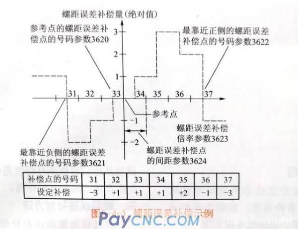
An example of pitch error compensation is shown in Figure 5-4-1.
1. Designation of compensation points
The compensation point of each axis is selected within the mechanical stroke range of the coordinate axis, and the reference point must be included in the compensation range. When the stroke of the machine exceeds the range specified on the positive side and the negative side, the pitch error compensation is not performed (all compensation amounts become 0).
2. Number of compensation point
A total of 1024 points are provided on the pitch error setting page, ranging from 0 to 1023, and the number is arbitrarily assigned to each axis through parameters.
Parameter 3620 is the number of the pitch error compensation point of each axis setting reference point, parameter 3621 sets the number of the pitch error compensation point closest to the negative side, and parameter 3622 sets the number of the pitch error compensation point closest to the positive side.
3. Spacing of compensation points
The compensation points of the pitch error compensation are equally spaced, which is set in parameter 3624 for each axis.
The pitch error compensation point has a minimum limit, which is determined by the following formula:
①Minimum value of pitch error compensation point pitch = maximum feed rate (rapid traverse speed) /7500
②The minimum value of pitch error compensation point pitch can be selected in mm, in, (.)
③The optional units of the maximum feed rate are mm/min, in/min, (.)/min.
For example, when the maximum feed rate is 15000 mm/min, the minimum pitch of the pitch error compensation points is 2 mm.
①The ball screw pair is at the last stage of the transmission chain of the feed system. There are various errors in the screw and nut, such as the cumulative error of the thread pitch, the error of the thread raceway, the error of the diameter, etc. The cumulative error of the screw pitch will be Cause the deviation of the target value of the machine tool.
②During the assembly process of the ball screw, due to the dual support structure, the screw is elongated in the axial direction, resulting in an increase in the error of the screw pitch and a deviation of the target value of the machine tool.
③In the assembly process of the machine tool, the error of the parallelism between the screw axis and the machine tool guide rail will cause the deviation of the target value of the machine tool.
Second, the role of pitch error compensation
Pitch error compensation increases or decreases the number of pulses of the command value by adjusting the parameters of the numerical control system, so that the actual movement distance of the machine tool is close to the command movement distance to improve the positioning accuracy of the machine tool. The pitch error compensation only works on the compensation section of the machine tool, and it plays a compensation role within the range allowed by the numerical control system.
3. Pitch error compensation method
By setting the pitch error compensation data, the detection unit of each axis is compensated. Use the position returned by the reference point as the compensation origin to set the compensation interval on each axis. Set the compensation value equivalent to the number of compensation points in the pitch error compensation data. Pitch error compensation data can also be set with external I/O devices (such as Handy File) (see user manual), and it can also be set directly through the MDI panel.
In the pitch error compensation, the following parameters need to be set. For the number of pitch error compensation points set with these parameters, the pitch error compensation amount needs to be set. See the table below for pitch error compensation parameters.
An example of pitch error compensation is shown in Figure 5-4-1.
1. Designation of compensation points
The compensation point of each axis is selected within the mechanical stroke range of the coordinate axis, and the reference point must be included in the compensation range. When the stroke of the machine exceeds the range specified on the positive side and the negative side, the pitch error compensation is not performed (all compensation amounts become 0).
2. Number of compensation point
A total of 1024 points are provided on the pitch error setting page, ranging from 0 to 1023, and the number is arbitrarily assigned to each axis through parameters.
Parameter 3620 is the number of the pitch error compensation point of each axis setting reference point, parameter 3621 sets the number of the pitch error compensation point closest to the negative side, and parameter 3622 sets the number of the pitch error compensation point closest to the positive side.
3. Spacing of compensation points
The compensation points of the pitch error compensation are equally spaced, which is set in parameter 3624 for each axis.
The pitch error compensation point has a minimum limit, which is determined by the following formula:
①Minimum value of pitch error compensation point pitch = maximum feed rate (rapid traverse speed) /7500
②The minimum value of pitch error compensation point pitch can be selected in mm, in, (.)
③The optional units of the maximum feed rate are mm/min, in/min, (.)/min.
For example, when the maximum feed rate is 15000 mm/min, the minimum pitch of the pitch error compensation points is 2 mm.