USD
USD
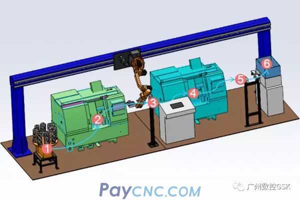
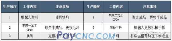
The loading bin is filled manually, and the robot sequentially grabs the blanks to be added one by one;
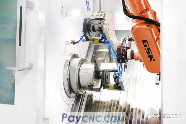
The air gripper 1 of the robot gripper 1 grabs the blanks and waits outside the door of the lathe 1. The semi-finished product processing in the lathe 1 is completed, the door of the lathe is opened, the air gripper 2 removes the semi-finished product after the lathe 1 is completed, and replaces the upper gripper 1 For the rough parts, the robot grabs the lathe one, the door of the lathe is closed, and the OP10 starts to process OP10;
The gripper 2 of the robot gripper 1 puts the semi-finished product on one side of the reversing table, and then uses the gripper 1 to grab the semi-finished product from the other side; the gripper 1 of the robot gripper 1 grabs the semi-finished product and waits outside the second door of the lathe. The machining of the second workpiece is completed, the second door of the lathe is opened, the gripper 2 removes the finished product of the second lathe, and the semi-finished product of the upper gripper 1 is replaced. The robot grips the second lathe, the second door of the lathe is closed, and the second lathe starts to process OP20. ;
The finished product of the air gripper 2 of the robot gripper 1 is transported to the temporary storage table of the gripping placing table, and the robot is replaced with the robot gripper 2;
The gripper 3 of the robot gripper 2 transports the finished product to the unloading bin;
The robot is replaced with a manipulator 1;
Repeat the above steps.
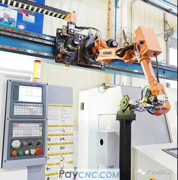
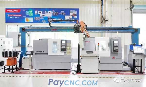
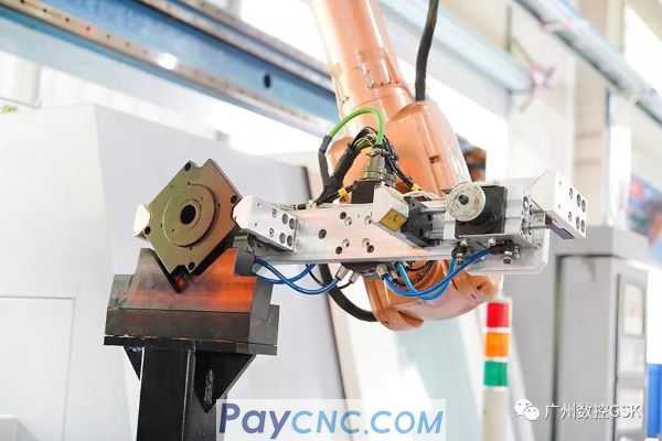
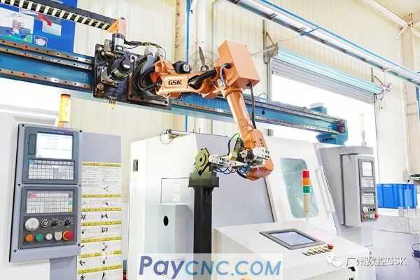
The GSK RB08A3 robot uses the end double-clamping tool to grasp the motor end cover and feed it to the machine tool for processing on the truss. At the same time, it realizes automatic cutting.
Specifications ·
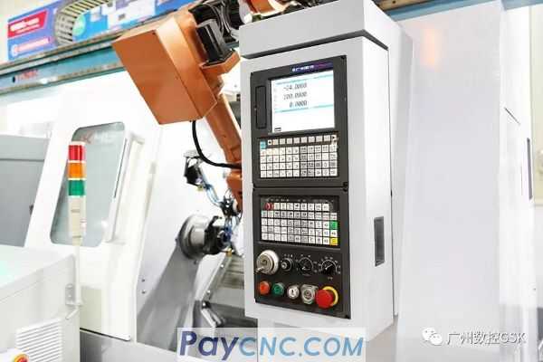
GSKRB08A3 Universal Robot
Number of moving axes: 6 axes
Maximum payload: 8KG
Repeated positioning accuracy: ± 0.05mm
Handling robots are widely used in automatic handling systems such as machine loading and unloading, and press production lines;
· Product advantages ·
Improved machine utilization and product quality;
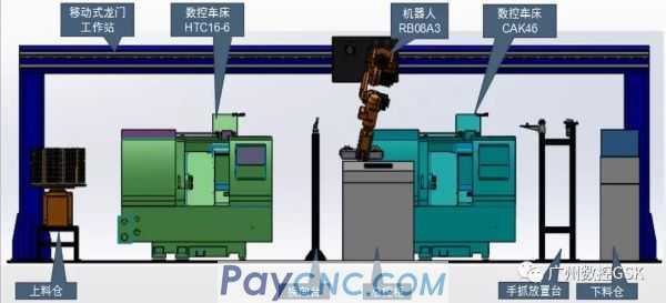
Set two sets of grips, one for loading and unloading, and the other for packing. Use quick-change tools to change between the grips;
High quality consistency reduces the risk of defective parts brought by workers;
The gantry mobile workstation makes full use of the upper space of the machine tool, freeing up ground work space, facilitating the maintenance of equipment such as machine tools, and a higher utilization rate of equipment compared to general automation solutions.
Loading silo
The automatic wire rack uses a laminated rotary rack. While ensuring the accuracy of loading, the positioning column needs to be adjusted when replacing different types of parts. As shown in the figure, the stacked rotary rack is controlled by a servo motor and the system.
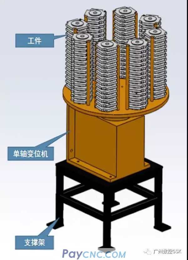
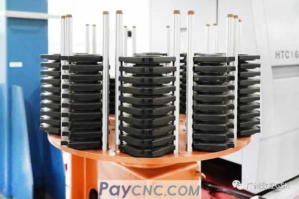
The worker leaves the silo full of blanks and leaves.
When working, the robot grabs the blanks from top to bottom. After the stack of blanks is grasped, the storage rack automatically rotates one station.
The sensor on the storage rack can automatically detect the material level. If the sensor does not detect the material for one minute, it will send a warning signal to remind the worker to add material to the silo.
If no material is detected for three minutes, a signal is sent to stop the machine. The whole machine is designed with multiple protections, which is safe and reliable.
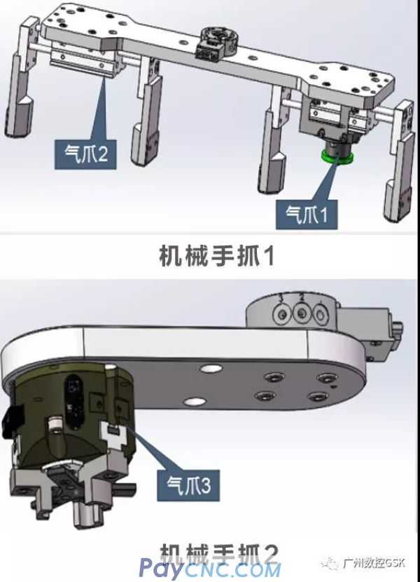
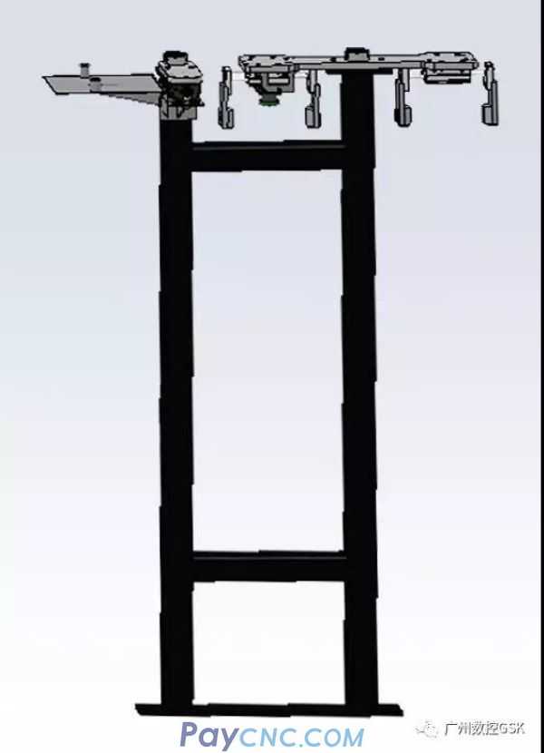
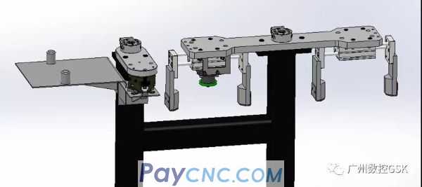
Robotic grip
According to the placement of the workpiece in the machine tool fixture and the silo, 2 sets of grippers are required to meet the production needs
Tooling instructions
Manipulator grip 1 adopts double gripper structure to realize rapid replacement of workpieces on the machine tool, which greatly saves material replacement time and improves machine tool utilization
Manipulator grip 2 adopts single gripper structure, which can move flexibly after gripping the workpiece, and can neatly place the workpiece in the lower bin
Commutator
The structure of the reversing station is shown in the figure on the right. The structure is simple and the cost is low.
The robot places the workpiece on a reversing table and then grabs the workpiece from the other side
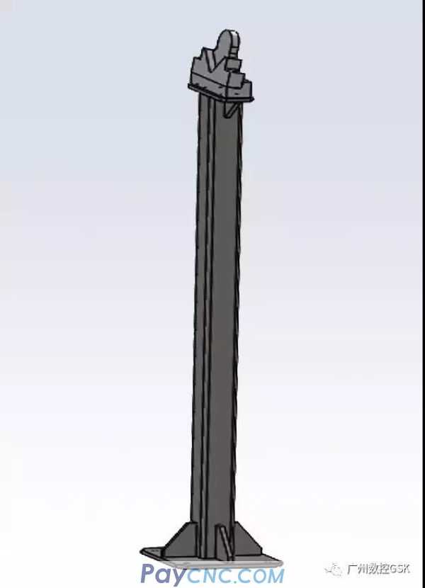
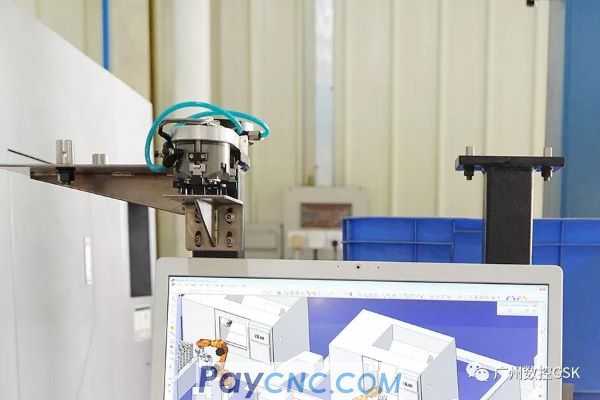
Quick change bracket
The structure of the hand-holding table is shown in the left figure, and the structure is simple and practical
work process ·
During work, the robot puts the workpiece on the temporary storage table. The robot moves the gripper 1 to the corresponding position, releases the quick-change device, and then moves to the top of the gripper 2 and closes the quick-change device. To replace the gripper
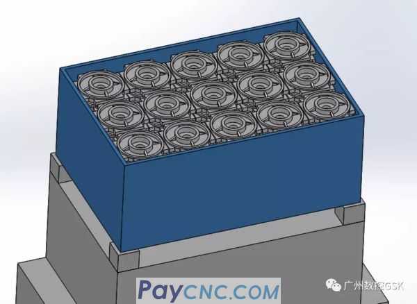
Unloading silo
The structure of the unloading bin is shown in the figure, the structure is simple and practical
· work process ·
Put the empty box on the positioning bracket manually;
During work, programming is performed by the robot's teach pendant, and the robot automatically palletizes the finished product;
When the box is full, use a forklift to fork it away manually.