USD
USD
How to deal with the tool wear
In order to achieve better cutting quality and the longest possible tool life, we need to check the inserts after processing, summarize the causes of different forms of insert wear and find solutions, which are the basis for successful milling.
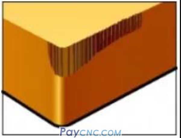
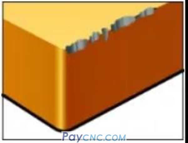
Flank wear 1
Rapid wear leads to poor surface quality or out of tolerance.
the reason
Cutting speed is too high
Insufficient wear resistance
Feed fz is too low
solution
Reduce cutting speed (vc)
Choose a material with higher wear resistance
Increase feed (fz)
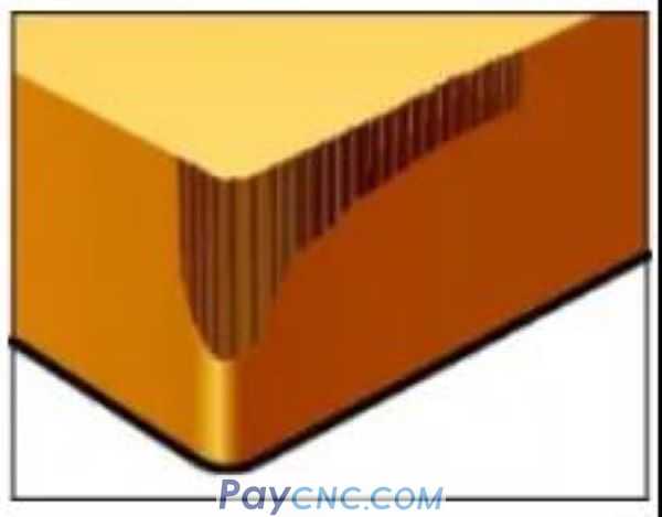
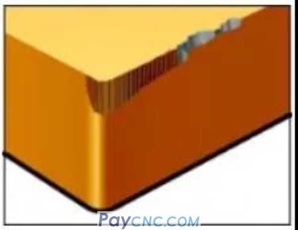
Flank wear 2
Excessive wear leads to short tool life.
the reason
vibration
Chip recut
Burrs are formed on parts
Poor surface quality
Generate heat
solution
Increase feed (fz)
Down milling
Use compressed air to effectively remove chips
Check recommended cutting parameters
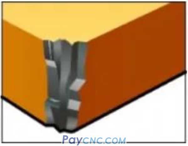
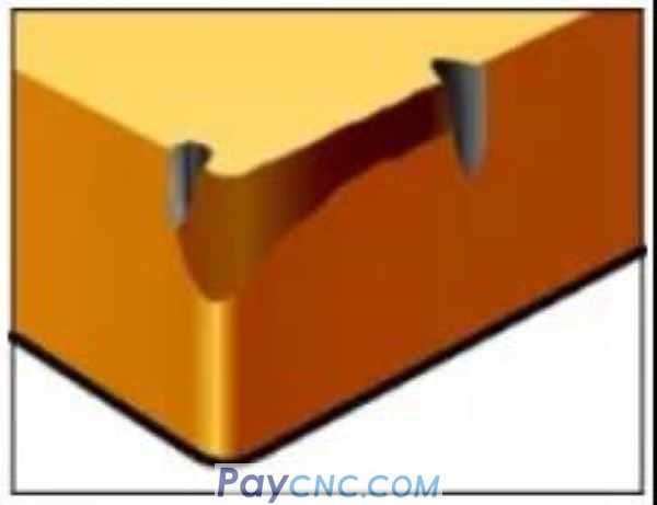
Flank wear 3
Uneven wear leads to damage to sharp corners.
the reason
Tool runout
vibration
Short tool life
Poor surface quality
loud noise
Radial force is too high
solution
Reduce the amount of runout to be less than 0.02 mm
Check chuck and jacket
Minimize tool extension
Use fewer teeth for cutting
Choose a larger tool diameter
For solid carbide end mills and interchangeable head milling cutters, choose a geometry with a larger helix angle (gp ≥45°)
Divide the axial depth of cut (ap) into multiple passes
Reduce feed (fz)
Reduce cutting speed (vc)
High-speed machining requires shallow passes
Improve tool and workpiece clamping
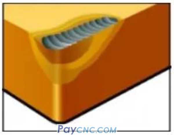
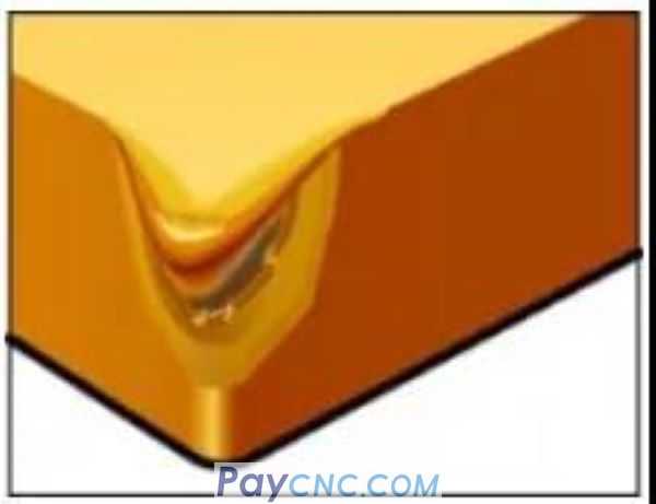
Crescent crater wear
Excessive wear leads to reduced cutting edge strength. Damaged cutting edges result in poor surface quality.
the reason
Diffusion wear caused by excessive cutting temperature of the rake face
solution
Choose alumina coating material
Use positive rake angle blade geometry
Reduce the speed to get a lower temperature, then reduce the feed
Plastic deformation
Plastic deformation of the cutting edge, sag, or recessed flank, resulting in poor chip control, poor surface quality, and blade breakage.
the reason
Cutting temperature and pressure are too high
solution
Choose a material with higher wear resistance (higher hardness)
Reduce cutting speed (vc)
Reduce feed (fz)
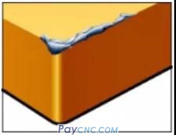
Chipping 1
The part where the cutting edge is not involved in cutting is damaged by chip hammering. Damage to the front and support surfaces of the blade, resulting in poor surface texture and excessive wear on the flank surface.
the reason
Chips are squeezed by the cutting edge
solution
Choose a grade with higher toughness
Choose inserts with stronger cutting edges
Increase cutting speed vc
Select positive rake angle geometry
Reduce feed at the beginning of cutting
Improve stability
Chipping 2
A small part of the cutting edge is broken (crushed) resulting in poor surface quality and excessive wear on the flank.
the reason
Material toughness is too low
The blade geometry is too weak
Buildup
solution
Choose a grade with higher toughness
Choose an insert with a stronger geometry
Increase the cutting speed vc, or choose a positive rake geometry
Reduce feed at the beginning of cutting
Groove wear
Groove wear leads to poor surface quality and the risk of cutting edge fracture.
the reason
Work hardened material
Epidermis and oxide skin
solution
Reduce cutting speed (vc)
Choose a grade with higher toughness
Use a stronger geometry
Use a cutting angle closer to 45°
Use round blades to ensure best results
Use variable AP technology to delay wear
Hot crack
Due to temperature changes, small cracks perpendicular to the cutting edge cause chipping and poor surface quality
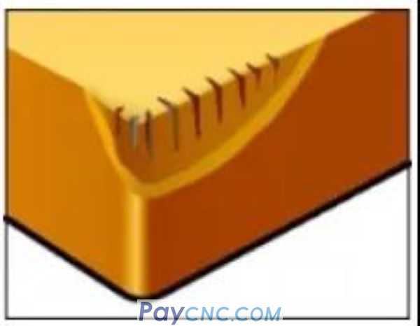
the reason
Intermittent processing
Changing cutting fluid supply
solution
Choose a material with higher toughness and better thermal shock resistance
Cutting fluid should be used in sufficient amount or not at all
Built-up tumor 1
The built-up edge leads to poor surface quality and causes the cutting edge to chip when it falls off.
the reason
The temperature in the cutting area is too low
Materials with very high viscosity, such as mild steel, stainless steel and aluminum
solution
Increase cutting speed vc
Change to a more suitable blade geometry
Built-up tumor 2
The workpiece material is welded to the cutting edge.

the reason
Low cutting speed vc
Low feed fz
Negative rake angle cutting geometry
Poor surface quality
solution
Increase cutting speed vc
Increase feed (fz)
Select positive rake angle geometry
Use oil mist or cutting fluid
Flank wear 1
Rapid wear leads to poor surface quality or out of tolerance.
the reason
Cutting speed is too high
Insufficient wear resistance
Feed fz is too low
solution
Reduce cutting speed (vc)
Choose a material with higher wear resistance
Increase feed (fz)
Flank wear 2
Excessive wear leads to short tool life.
the reason
vibration
Chip recut
Burrs are formed on parts
Poor surface quality
Generate heat
solution
Increase feed (fz)
Down milling
Use compressed air to effectively remove chips
Check recommended cutting parameters
Flank wear 3
Uneven wear leads to damage to sharp corners.
the reason
Tool runout
vibration
Short tool life
Poor surface quality
loud noise
Radial force is too high
solution
Reduce the amount of runout to be less than 0.02 mm
Check chuck and jacket
Minimize tool extension
Use fewer teeth for cutting
Choose a larger tool diameter
For solid carbide end mills and interchangeable head milling cutters, choose a geometry with a larger helix angle (gp ≥45°)
Divide the axial depth of cut (ap) into multiple passes
Reduce feed (fz)
Reduce cutting speed (vc)
High-speed machining requires shallow passes
Improve tool and workpiece clamping
Crescent crater wear
Excessive wear leads to reduced cutting edge strength. Damaged cutting edges result in poor surface quality.
the reason
Diffusion wear caused by excessive cutting temperature of the rake face
solution
Choose alumina coating material
Use positive rake angle blade geometry
Reduce the speed to get a lower temperature, then reduce the feed
Plastic deformation
Plastic deformation of the cutting edge, sag, or recessed flank, resulting in poor chip control, poor surface quality, and blade breakage.
the reason
Cutting temperature and pressure are too high
solution
Choose a material with higher wear resistance (higher hardness)
Reduce cutting speed (vc)
Reduce feed (fz)
Chipping 1
The part where the cutting edge is not involved in cutting is damaged by chip hammering. Damage to the front and support surfaces of the blade, resulting in poor surface texture and excessive wear on the flank surface.
the reason
Chips are squeezed by the cutting edge
solution
Choose a grade with higher toughness
Choose inserts with stronger cutting edges
Increase cutting speed vc
Select positive rake angle geometry
Reduce feed at the beginning of cutting
Improve stability
Chipping 2
A small part of the cutting edge is broken (crushed) resulting in poor surface quality and excessive wear on the flank.
the reason
Material toughness is too low
The blade geometry is too weak
Buildup
solution
Choose a grade with higher toughness
Choose an insert with a stronger geometry
Increase the cutting speed vc, or choose a positive rake geometry
Reduce feed at the beginning of cutting
Groove wear
Groove wear leads to poor surface quality and the risk of cutting edge fracture.
the reason
Work hardened material
Epidermis and oxide skin
solution
Reduce cutting speed (vc)
Choose a grade with higher toughness
Use a stronger geometry
Use a cutting angle closer to 45°
Use round blades to ensure best results
Use variable AP technology to delay wear
Hot crack
Due to temperature changes, small cracks perpendicular to the cutting edge cause chipping and poor surface quality
the reason
Intermittent processing
Changing cutting fluid supply
solution
Choose a material with higher toughness and better thermal shock resistance
Cutting fluid should be used in sufficient amount or not at all
Built-up tumor 1
The built-up edge leads to poor surface quality and causes the cutting edge to chip when it falls off.
the reason
The temperature in the cutting area is too low
Materials with very high viscosity, such as mild steel, stainless steel and aluminum
solution
Increase cutting speed vc
Change to a more suitable blade geometry
Built-up tumor 2
The workpiece material is welded to the cutting edge.
the reason
Low cutting speed vc
Low feed fz
Negative rake angle cutting geometry
Poor surface quality
solution
Increase cutting speed vc
Increase feed (fz)
Select positive rake angle geometry
Use oil mist or cutting fluid