USD
USD
How to overcome deformation when turning Thin-walled Parts
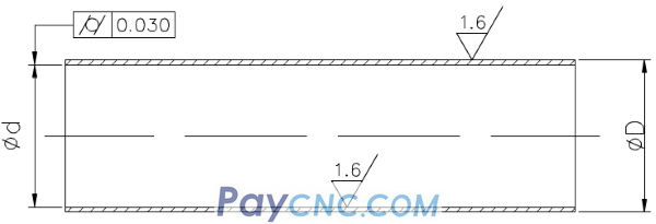
In the cutting process, the thin wall is easily deformed by the cutting force, which leads to an oval or a "waist shape" with a small middle and large ends. In addition, thin-walled bushings are prone to thermal deformation due to poor heat dissipation during processing, and it is difficult to ensure the processing quality of parts. The parts shown in the figure below are not only inconvenient to install and clamp, but also difficult to process the processed parts. It is necessary to design a special thin-walled casing and shaft guard.
▌ Process analysis
According to the technical requirements provided by the drawings, the workpiece is processed by seamless steel pipes. The surface roughness of the inner hole and outer wall is Ra1.6μm, which can be achieved by turning, but the cylindricity of the inner hole is 0.03mm, which is required for thin-walled parts Higher. In mass production, the process route is roughly: blanking-heat treatment-car end face-car outer circle-car inner hole-quality inspection.
The "inner hole machining" process is the key to quality control. It is difficult to guarantee a 0.03mm cylinder without the outer circle and thin-walled casing.
▌ The key technology of car hole
The key technology of turning holes is to solve the rigidity and chip removal problems of the inner hole turning tools. To increase the rigidity of the inner hole turning tool, take the following measures:
(1) Try to increase the cross-sectional area of the tool holder, usually the tip of the inner hole turning tool is located on the top of the tool holder, so the cross-sectional area of the tool holder is less, less than 1/4 of the cross-sectional area of the hole, as shown in the left figure below . If the tip of the inner hole turning tool is located on the center line of the tool holder, the cross-sectional area of the tool holder in the hole can be greatly increased, as shown in the right figure below.

(2) The extension length of the tool holder should be as long as 5-8mm as the length of the workpiece to be processed, so as to increase the rigidity of the tool holder and reduce the vibration during the cutting process.
▌ Solve the problem of chip removal
It mainly controls the cutting outflow direction. The rough turning tool requires the chips to flow to the surface to be processed (front chip removal). For this reason, the inner hole turning tool with a positive edge inclination is used, as shown in the figure below.
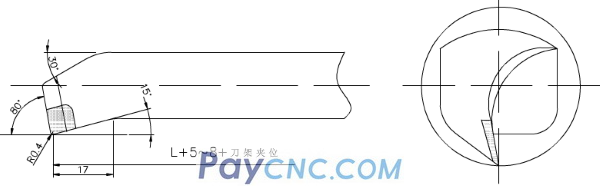
When finishing turning, it is required that the chips flow to the center to tilt the chip forward (the hole core chip removal), so when sharpening the tool, pay attention to the grinding direction of the cutting edge, and the chip removal method of inclination to the front edge, as shown in the figure below. The knife alloy uses YA6, the current M type, which has better bending strength, wear resistance, impact toughness, and resistance to steel and temperature.
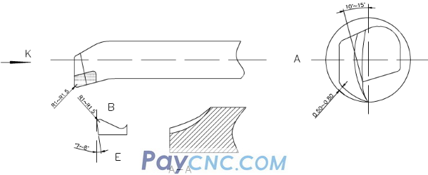
When sharpening, the rake angle is rounded with an arc-like angle of 10-15°, the back angle is 0.5-0.8mm away from the wall according to the machining arc (the bottom line of the tool is along the radian), c cutting edge angle k direction is §0.5-1 as the edge The wiper at point B of the chip edge is R1-1.5, the auxiliary relief angle is ground to 7-8°, and the point AA of the E inner edge is ground into a circle to remove chips.
▌ Processing method
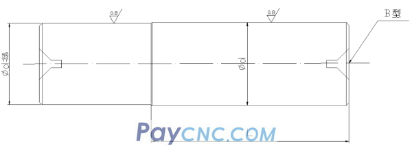
(1) A shaft guard must be made before processing. The main purpose of the shaft guard is to cover the inner hole of the thin-walled sleeve of the car in the original size, and fix it with the front and rear centers to process the outer circle without deformation, and to maintain the quality and accuracy of the outer circle. Therefore, the processing of the shaft guard is a key link in the process of processing the thin-walled casing.
45﹟Carbon structure round steel is used for processing the shaft guard blank; the end face of the car, two B-shaped center holes are opened, the outer circle is rough, and the margin is 1mm. After heat treatment, tempering and shaping, add WeChat: Yuki7557, send a copy of macro program tutorial, and then leave 0.2mm margin for grinding. Re-heat the broken fire surface to a hardness of HRC50, and then grind it with a cylindrical grinder as shown in the figure below. The accuracy meets the requirements and it will be used after completion.
(2) In order to complete the processing of the workpiece at one time, the blank retains the clamping position and cutting margin.
(3) Firstly, the rough embryo is heat-treated, quenched, tempered and shaped, with a hardness of HRC28-30 (hardness within the processing range).
(4) The turning tool adopts C620. First, put the front center into the spindle cone and fix it. In order to prevent the deformation of the workpiece when clamping the thin-walled sleeve, add an open-loop thick sleeve, as shown in the figure below.

In order to maintain mass production, the outer end of the thin-walled casing is processed to a uniform size d, the ruler of t is the axial clamping position, and the thin-walled casing is compressed to improve the quality of the inner hole of the car and maintain the size. Considering that cutting heat is generated, the expansion size of the workpiece is difficult to grasp. It is necessary to pour sufficient cutting fluid to reduce the thermal deformation of the workpiece.
(5) Clamp the workpiece firmly with an automatic centering three-jaw chuck, turn the end face, and rough turn the inner circle. Leave a margin of 0.1-0.2mm for fine turning, and replace it with a fine turning tool to process the cutting margin until the guard shaft meets the requirements of excessive fit and roughness. Remove the inner hole turning tool, insert the guard shaft to the front center, use the tailstock center to clamp according to the length requirements, replace the external turning tool to roughen the outer circle, and then finish turning to the drawing requirements. After passing the inspection, use a cutting knife to cut according to the required length. In order to make the cut smooth when the workpiece is disconnected, the cutting edge should be slanted to make the end face of the workpiece smooth; the small part of the guard shaft is to be ground to reduce the gap left by the cutting, and the guard shaft is to reduce the deformation of the workpiece, prevent vibration, and when cutting The reason for falling and bruising.
▌ Conclusion
The above method for processing thin-walled casings solves the problem of deformation or causing size and shape errors that fail to meet the requirements. Practice has proved that the processing efficiency is high, easy to operate, and suitable for processing long thin-walled parts, and the size is easy to grasp. It is completed in second time and mass production is more practical.
▌ Process analysis
According to the technical requirements provided by the drawings, the workpiece is processed by seamless steel pipes. The surface roughness of the inner hole and outer wall is Ra1.6μm, which can be achieved by turning, but the cylindricity of the inner hole is 0.03mm, which is required for thin-walled parts Higher. In mass production, the process route is roughly: blanking-heat treatment-car end face-car outer circle-car inner hole-quality inspection.
The "inner hole machining" process is the key to quality control. It is difficult to guarantee a 0.03mm cylinder without the outer circle and thin-walled casing.
▌ The key technology of car hole
The key technology of turning holes is to solve the rigidity and chip removal problems of the inner hole turning tools. To increase the rigidity of the inner hole turning tool, take the following measures:
(1) Try to increase the cross-sectional area of the tool holder, usually the tip of the inner hole turning tool is located on the top of the tool holder, so the cross-sectional area of the tool holder is less, less than 1/4 of the cross-sectional area of the hole, as shown in the left figure below . If the tip of the inner hole turning tool is located on the center line of the tool holder, the cross-sectional area of the tool holder in the hole can be greatly increased, as shown in the right figure below.
(2) The extension length of the tool holder should be as long as 5-8mm as the length of the workpiece to be processed, so as to increase the rigidity of the tool holder and reduce the vibration during the cutting process.
▌ Solve the problem of chip removal
It mainly controls the cutting outflow direction. The rough turning tool requires the chips to flow to the surface to be processed (front chip removal). For this reason, the inner hole turning tool with a positive edge inclination is used, as shown in the figure below.
When finishing turning, it is required that the chips flow to the center to tilt the chip forward (the hole core chip removal), so when sharpening the tool, pay attention to the grinding direction of the cutting edge, and the chip removal method of inclination to the front edge, as shown in the figure below. The knife alloy uses YA6, the current M type, which has better bending strength, wear resistance, impact toughness, and resistance to steel and temperature.
When sharpening, the rake angle is rounded with an arc-like angle of 10-15°, the back angle is 0.5-0.8mm away from the wall according to the machining arc (the bottom line of the tool is along the radian), c cutting edge angle k direction is §0.5-1 as the edge The wiper at point B of the chip edge is R1-1.5, the auxiliary relief angle is ground to 7-8°, and the point AA of the E inner edge is ground into a circle to remove chips.
▌ Processing method
(1) A shaft guard must be made before processing. The main purpose of the shaft guard is to cover the inner hole of the thin-walled sleeve of the car in the original size, and fix it with the front and rear centers to process the outer circle without deformation, and to maintain the quality and accuracy of the outer circle. Therefore, the processing of the shaft guard is a key link in the process of processing the thin-walled casing.
45﹟Carbon structure round steel is used for processing the shaft guard blank; the end face of the car, two B-shaped center holes are opened, the outer circle is rough, and the margin is 1mm. After heat treatment, tempering and shaping, add WeChat: Yuki7557, send a copy of macro program tutorial, and then leave 0.2mm margin for grinding. Re-heat the broken fire surface to a hardness of HRC50, and then grind it with a cylindrical grinder as shown in the figure below. The accuracy meets the requirements and it will be used after completion.
(2) In order to complete the processing of the workpiece at one time, the blank retains the clamping position and cutting margin.
(3) Firstly, the rough embryo is heat-treated, quenched, tempered and shaped, with a hardness of HRC28-30 (hardness within the processing range).
(4) The turning tool adopts C620. First, put the front center into the spindle cone and fix it. In order to prevent the deformation of the workpiece when clamping the thin-walled sleeve, add an open-loop thick sleeve, as shown in the figure below.
In order to maintain mass production, the outer end of the thin-walled casing is processed to a uniform size d, the ruler of t is the axial clamping position, and the thin-walled casing is compressed to improve the quality of the inner hole of the car and maintain the size. Considering that cutting heat is generated, the expansion size of the workpiece is difficult to grasp. It is necessary to pour sufficient cutting fluid to reduce the thermal deformation of the workpiece.
(5) Clamp the workpiece firmly with an automatic centering three-jaw chuck, turn the end face, and rough turn the inner circle. Leave a margin of 0.1-0.2mm for fine turning, and replace it with a fine turning tool to process the cutting margin until the guard shaft meets the requirements of excessive fit and roughness. Remove the inner hole turning tool, insert the guard shaft to the front center, use the tailstock center to clamp according to the length requirements, replace the external turning tool to roughen the outer circle, and then finish turning to the drawing requirements. After passing the inspection, use a cutting knife to cut according to the required length. In order to make the cut smooth when the workpiece is disconnected, the cutting edge should be slanted to make the end face of the workpiece smooth; the small part of the guard shaft is to be ground to reduce the gap left by the cutting, and the guard shaft is to reduce the deformation of the workpiece, prevent vibration, and when cutting The reason for falling and bruising.
▌ Conclusion
The above method for processing thin-walled casings solves the problem of deformation or causing size and shape errors that fail to meet the requirements. Practice has proved that the processing efficiency is high, easy to operate, and suitable for processing long thin-walled parts, and the size is easy to grasp. It is completed in second time and mass production is more practical.