USD
USD
How to replace an absolute encoder inside the AC servo motor

Introduction: In the use process and installation of the motor, the encoder will be damaged and need to be replaced. After the encoder is replaced, the synchronous motor needs to be zeroed before the encoder can be used normally. The following introduces the steps of encoder disassembly and zero adjustment. Use the GR servo drive to perform encoder zero adjustment.
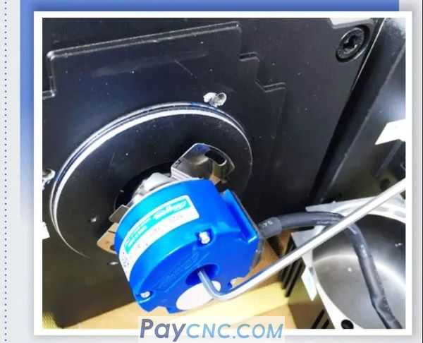
01 Disassembly and assembly of encoder
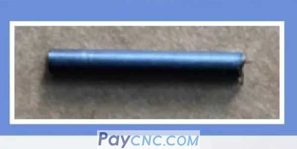
First prepare the auxiliary tool for removing the encoder to facilitate removal of the tapered encoder. This tool can be placed in the rear slot of the motor in the middle of the encoder and then screwed against it, using the reaction force to easily eject the encoder.
Auxiliary tool: metal rod length: 23mm diameter: 3mm
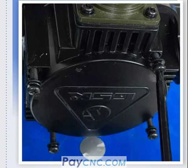
Remove the four screws on the rear cover of the motor and remove the rear cover.
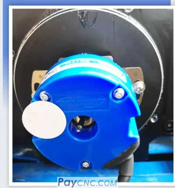
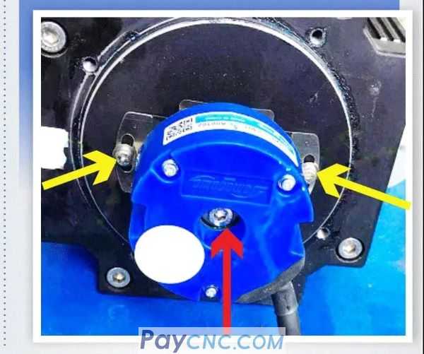
Remove the two screws that fix the encoder metal sheet and the screws that lock the encoder shaft. As indicated by the yellow and red arrows.

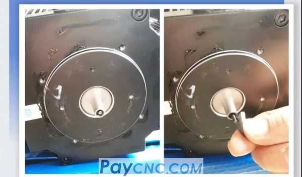
Insert the prepared metal rod into the center hole of the encoder.
Use the prepared hexagon socket screws to rotate the center hole of the encoder.
Auxiliary tool: inner 6 angle screw
Length: 30mm
Diameter: 5-threaded screw
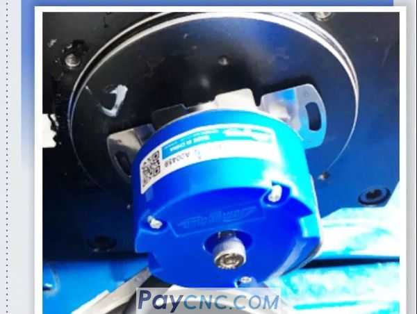
Hold the motor shaft in the left hand, and use a hex wrench to tighten the screw with the right hand. The encoder is quickly removed.
After the encoder is removed, the metal rod can be easily sucked out with a small magnet. When there is no magnet, lift the motor by hand to tilt the motor, and the metal bar will usually fall out. Auxiliary tool: small magnet
To install a new encoder, first align the metal pieces on both sides of the encoder with the mounting screw holes and tighten the screws. Then use the screw that just removed the encoder to lock the connection between the encoder shaft and the motor shaft.
02 Encoder Zero
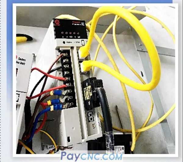
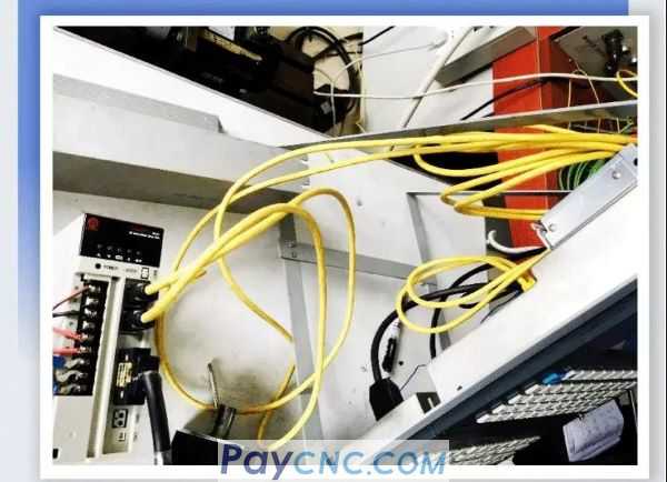
After the replacement of the new encoder is complete, the next step can be carried out—encoder zero adjustment. Before zero adjustment, ensure that the motor is disconnected from the load and controlled by the system. The driver of the disconnected system control will display an alarm for disconnection of the network cable. The following steps can eliminate the alarm.
The first method: short-circuit the network cable in order to eliminate the alarm of the driver network cable connection after power-on; the second method: change PA4 to 11 and save and restart. However, the E-43 alarm may occasionally appear after replacing the new encoder. In this case, the alarm can be eliminated by the third electrical step at the end of the article.
The short-circuited network cable in the figure can use the network cable connected between the driver and the driver.
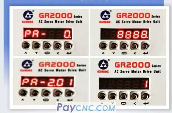
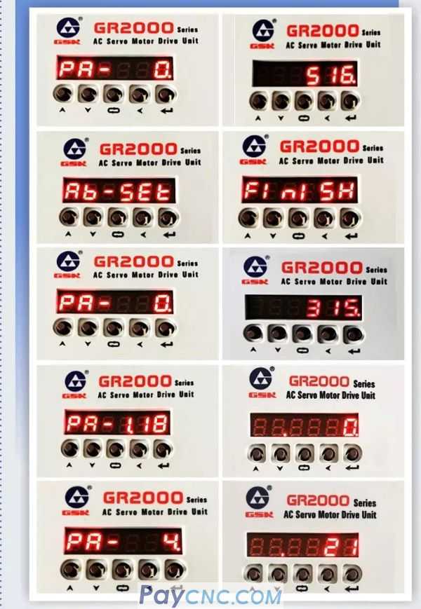
PA0=8888S Set PA201=1 (automatic zero adjustment)
PA4=11 (zero adjustment mode)-PA118=1 (forced enable)
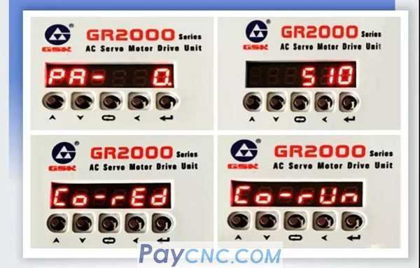
PA0=510 (zero code)-CO-red-CO-run, the motor rotates after pressing Enter
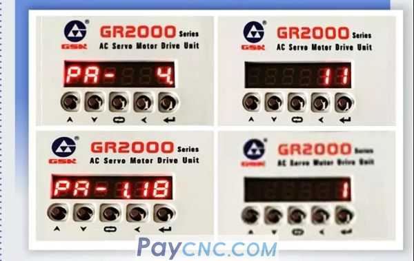
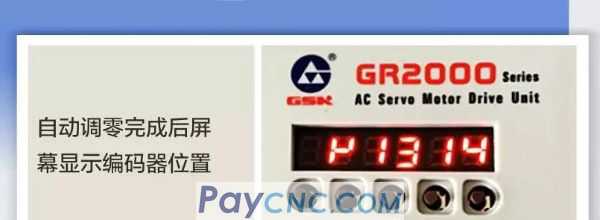
After the motor stops rotating and the screen shows zero adjustment data, complete the following steps within 40 seconds or E-22 will appear.
Set PA0=516-Ab-set-FINISH-PA0=315-PA118=0-PA4=21
Note: PA4 and PA118 must be restored to the data before zero adjustment after zero adjustment.
Disconnect the power line and restore it to the original state, then power on
Restoring the original state refers to the connection sequence of the machine tool network cable before the end of the network port is shorted
03 E-43 appears after replacing the encoder
PA0=8888 Confirm PA201=1 (automatic zero adjustment)
PA118=0 (no enable state)
PA0=516-Ab-set-FINISH
After restarting, the alarm will be eliminated and then install the second step to perform the encoder zero adjustment operation.
04 Conclusion
The above are the detailed steps for the motor re-encoder damage and the need to disassemble the encoder and install the new encoder to adjust the zero.