USD
USD
How to set reference point on GSK 218MC

The machine tool coordinate system is the inherent coordinate system of the machine tool. The origin of the machine tool coordinate system is called the mechanical zero point (or machine zero point), also known as the reference point. It is the mechanical origin specified by the machine tool manufacturer and is usually installed on the X axis, Y axis, and Z axis. The maximum stroke in the positive direction of the axis, 4TH axis, and 5TH axis. When the CNC device is powered on, the mechanical zero point is not known, and the mechanical zero point is usually returned automatically or manually.
There are two types of zero return mode: 1. After the block;2. Before the block. It is set by bit parameter NO: 6#1.
There are two ways to return to zero: 1. One-turn signal; 2. No one-turn signal. It is set by bit parameter NO: 6#6.
When the motor has no one-turn signal during zero return, the zero return method is divided into two types: A type and B type. It is set by bit parameter NO: 6#7, the following describes the system zero setting method in detail:
01Operation steps for zero return of pulse type servo machinery
Press the zero key of the machine tool to enter the mechanical zero return operation mode. At this time, the word "mechanical zero return" is displayed on the lower right corner of the LCD screen film.
Select the X-axis, Y-axis, Z-axis, 4TH-axis or 5TH-axis to return to the mechanical zero point, and the zero return direction is set by bit parameter NO: 7~NO: 7#4.
The machine tool moves in the direction of the mechanical zero point. Before the deceleration point, the machine tool moves quickly (the moving speed is set by data parameters P100~P104). After the deceleration switch is encountered, the zero return speed of each axis is set by the data parameters P342~P346, and the gear is out of gear. After the block, it moves to the mechanical zero point (ie the reference point) at the speed of FL (set by data parameter P099). When returning to the mechanical zero point, the coordinate axis stops moving and the zero return indicator is on.
02soft limit parameter modification method
Set the bit parameter NO: 0#=1 to configure the GE series multi-turn absolute version, manually move each axis to the position of the machine zero point,
Press the system key to enter the system page, and switch to display the [+bus configuration] sub-interface through the corresponding soft key. See Figure 3-3-5-1 for details.
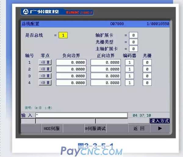
03 Press the [+Bus Configuration] soft key to enter the bus configuration interface as shown in Figure 3-3-5-1 and then view the parameters in it, and you can also modify the related parameters. The specific operation methods and steps are as follows:
Enter operation mode;
Press the up, down, left, and right keys to move the cursor to move it to the item to be changed;
Follow the instructions below to modify;
Bus
0: Drive unit transmission mode is pulse
1: The transmission mode of the drive unit is bus
Encoder type
0: Incremental 1: Absolute
Axis expansion card
0: No expansion card 1: With expansion card
Raster type
0: Incremental 1: Absolute
Spindle expansion card
0: No expansion card 1: With expansion card
Multi-turn absolute zero setting
First of all, set the gear ratio, feed axis direction and zero return direction on the system side, and power off again.
In MDI mode, in the bus configuration interface, set "Bus or not" to 1, "Encoder type" to 1, and manually move each axis to set the machine zero position.
Move the cursor to the setting, press the
Whether to configure grating. Set whether to configure grating for each axis, 0: no grating configuration, 1: grating configuration.
Press enter to confirm
Note 1: After the machine zero is set, if you modify the zero return direction of each axis of the system, the movement direction of the feed axis, the servo and the system gear ratio, the zero will be lost, and the machine zero must be reset.
Note 2: After the machine zero is reset, it will affect other reference points, such as the second and third reference points to be reset.
04 Conclusion
Through the above description, we can understand the problem of setting the mechanical zero point in the debugging process. The absolute encoder sets the zero point, and the zero position can be set according to the absolute position feedback from the motor.