USD
USD
Roundness tolerance
In addition to "English", the common international language, there is another thing that friends may not know, that is "shape and position tolerance".
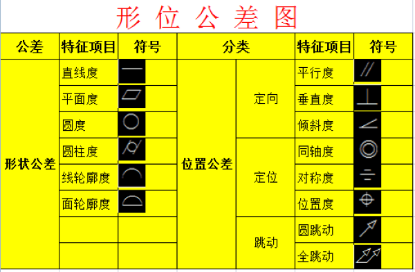
Geometric tolerances are regarded as an international language system because they run through the design, manufacturing, and quality management departments of the manufacturing industry.
In Europe in the 1980s, due to the existence of different standards, lawsuits that did not comply with the drawing instructions frequently occurred in the links of procurement and delivery. The original practice cannot adapt to the rapidly developing technology.
With the need for international cooperation and technical joint development, ISO/TC213 activities began: the international unification of geometric tolerances and their drawing symbols (drawing information) was carried out, and a working committee was introduced.
Today we will talk about the evaluation of roundness.
Roundness tolerance
Speaking of roundness, first we look at the representation and definition of the roundness tolerance zone:
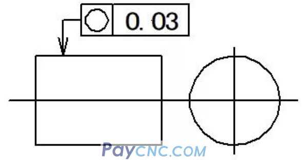

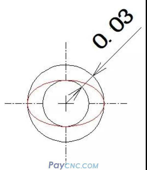
The tolerance zone for roundness is between two concentric circles on the same section. So how do you measure it?
Roundness measurement
For multiple measurement methods of roundness, we first need to solve the measurement principle first, and select the most suitable measurement method according to the actual workpiece evaluation requirements.
Simple measurement method
Diameter method
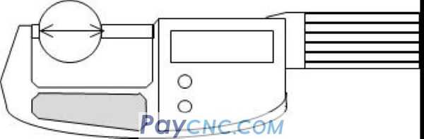
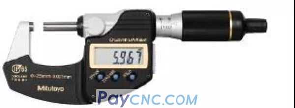
The diameter of the roundness can be directly read by measuring tools such as a micrometer. This simple measurement method is simple and easy to operate. However, when evaluating the equal-diameter strain circle, if it is not a perfect circle, it is easy to be mistakenly detected as a perfect circle.
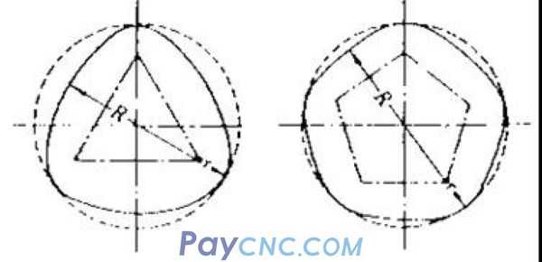
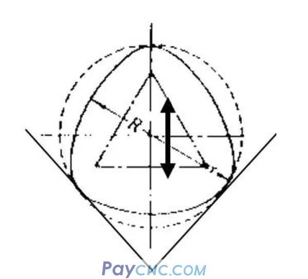
Three-point method
The three-point method can obtain roundness data through [V-shaped block + micrometer/meter + stand].
However, the tangents at the support points selected in the three-point method are different and may not be measured correctly. The center of the reference cannot be determined, and the up and down movement that occurs with the rotation of the measured object will cause an error.
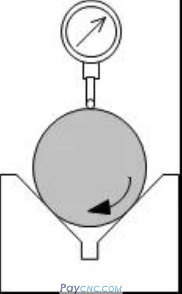
Radius method
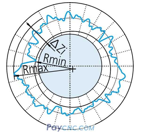
The radius method uses the difference between the maximum radius value and the minimum radius value obtained by one revolution of the workpiece to evaluate the roundness.
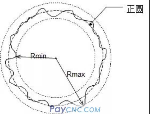
In this evaluation method as shown in the figure above, the measurement results are also easily affected by the horizontal operation of the workpiece.
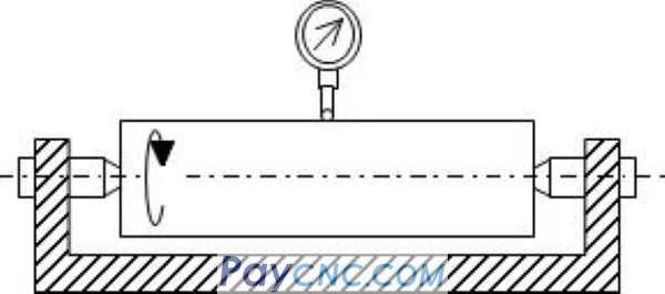
Central method
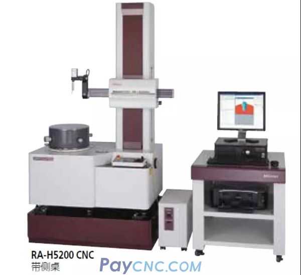
Compared with the detection method of the center method, it is mostly used for more precise measurement requirements. The roundness detection data depends on the reference circle, the selected reference circle evaluation method is different, the characteristic value of the roundness will be different.
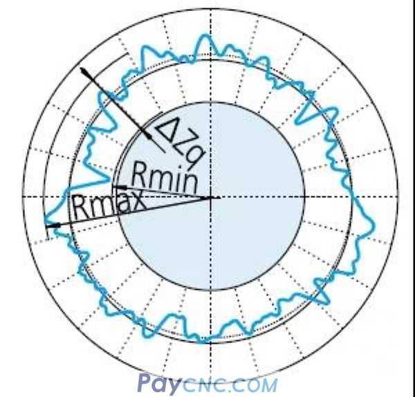
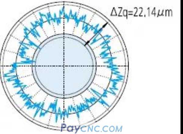
Least squares center method
<LSC・ΔZq>
Set a standard circle, the sum of the squares of the radius difference between this circle and the measured circle is the smallest, the center coordinate position of this reference circle is taken as the center of the measurement graph, and the two circles inscribed and circumscribed on the concentric measurement graph The difference in radius is roundness.
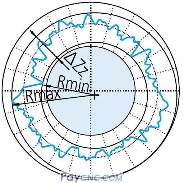
Minimum Area Center Method
<MZC・ΔZz>
Find the center coordinate position of the 2 circle with the smallest radius difference between the concentric circles of the 2 circles in the measurement graph, use this center coordinate as the center of the measurement graph, the difference between the radius of the 2 circles at this time is Is roundness.
(Evaluation method defined by JIS geometric tolerance).
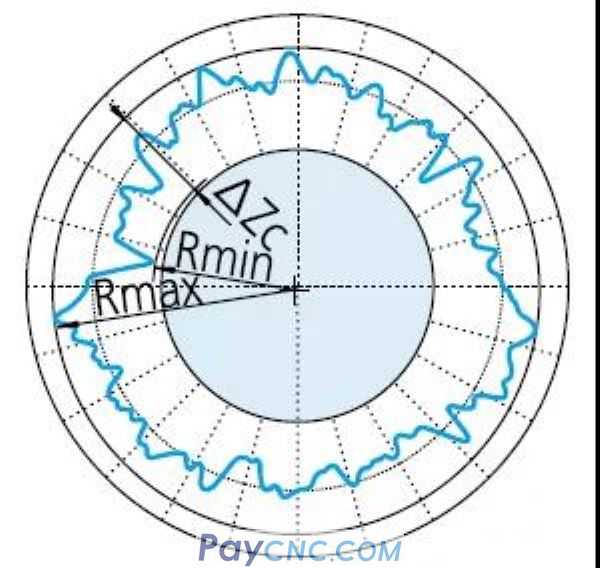
Minimum circumscribed circle center method
<MCC・ΔZc>
Set a circle that circumscribes the measured circle at 3 points on the measured circle, and use this circle as the center to make a circle inscribed with the measured circle. The radius difference between the two circles is the roundness.
It is often used in the evaluation of shafts and rods.
Maximum inscribed circle center method
<MIC・ΔZi>
Set a circle inscribed with the measured circle at 3 points on the measured circle, take this circle as the center, and then make a circle circumscribed with the measured circle. The radius difference between the two circles is the roundness.
The maximum inscribed circle center method is mostly used for hole evaluation.
Talking about the method of measuring roundness, filtering has to be mentioned again.
Influence of filter on measurement results
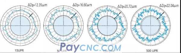
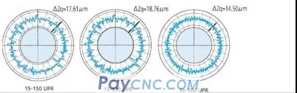
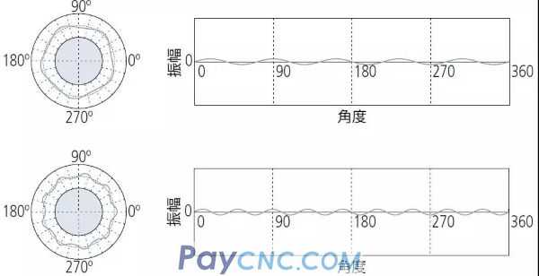
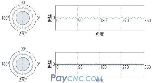
Because of the influence of various environments or other factors, in order to eliminate the noise, it is necessary to set the filter cut-off value when measuring the roundness. The following figure shows the influence of the filter on the measurement results.
So what information can we read out of the roundness measurement results?
Analysis of measurement charts
1UPR component (1 mountain/turn)
1 The UPR component represents the eccentricity of the workpiece relative to the rotation axis of the measuring instrument. The amplitude of the waveform depends on its level adjustment.
2UPR component (2 hills/turn)
The 2UPR component may indicate:
① The level adjustment of the measuring instrument is insufficient;
② Circular runout caused by incorrect installation of the workpiece on the machine tool that formed its shape;
③ The shape of the workpiece is elliptical in design, such as in IC engine pistons.
3~5UPR component (mountain/turn)
May mean:
① Deformation caused by too tight holding chuck on the measuring instrument.
②When unloading from the fixed chuck of the processing machine tool, the slack deformation caused by stress release.
5~15 UPR component (mountain/turn)
It usually indicates an unbalanced factor in the processing method or the process of producing the workpiece.
15 (more) UPR component (hill/turn)
15 (or more) UPR conditions are usually caused by tool chatter, machine vibration, coolant delivery effects, material inhomogeneity, etc.
Geometric tolerances are regarded as an international language system because they run through the design, manufacturing, and quality management departments of the manufacturing industry.
In Europe in the 1980s, due to the existence of different standards, lawsuits that did not comply with the drawing instructions frequently occurred in the links of procurement and delivery. The original practice cannot adapt to the rapidly developing technology.
With the need for international cooperation and technical joint development, ISO/TC213 activities began: the international unification of geometric tolerances and their drawing symbols (drawing information) was carried out, and a working committee was introduced.
Today we will talk about the evaluation of roundness.
Roundness tolerance
Speaking of roundness, first we look at the representation and definition of the roundness tolerance zone:
The tolerance zone for roundness is between two concentric circles on the same section. So how do you measure it?
Roundness measurement
For multiple measurement methods of roundness, we first need to solve the measurement principle first, and select the most suitable measurement method according to the actual workpiece evaluation requirements.
Simple measurement method
Diameter method
The diameter of the roundness can be directly read by measuring tools such as a micrometer. This simple measurement method is simple and easy to operate. However, when evaluating the equal-diameter strain circle, if it is not a perfect circle, it is easy to be mistakenly detected as a perfect circle.
Three-point method
The three-point method can obtain roundness data through [V-shaped block + micrometer/meter + stand].
However, the tangents at the support points selected in the three-point method are different and may not be measured correctly. The center of the reference cannot be determined, and the up and down movement that occurs with the rotation of the measured object will cause an error.
Radius method
The radius method uses the difference between the maximum radius value and the minimum radius value obtained by one revolution of the workpiece to evaluate the roundness.
In this evaluation method as shown in the figure above, the measurement results are also easily affected by the horizontal operation of the workpiece.
Central method
Compared with the detection method of the center method, it is mostly used for more precise measurement requirements. The roundness detection data depends on the reference circle, the selected reference circle evaluation method is different, the characteristic value of the roundness will be different.
Least squares center method
<LSC・ΔZq>
Set a standard circle, the sum of the squares of the radius difference between this circle and the measured circle is the smallest, the center coordinate position of this reference circle is taken as the center of the measurement graph, and the two circles inscribed and circumscribed on the concentric measurement graph The difference in radius is roundness.
Minimum Area Center Method
<MZC・ΔZz>
Find the center coordinate position of the 2 circle with the smallest radius difference between the concentric circles of the 2 circles in the measurement graph, use this center coordinate as the center of the measurement graph, the difference between the radius of the 2 circles at this time is Is roundness.
(Evaluation method defined by JIS geometric tolerance).
Minimum circumscribed circle center method
<MCC・ΔZc>
Set a circle that circumscribes the measured circle at 3 points on the measured circle, and use this circle as the center to make a circle inscribed with the measured circle. The radius difference between the two circles is the roundness.
It is often used in the evaluation of shafts and rods.
Maximum inscribed circle center method
<MIC・ΔZi>
Set a circle inscribed with the measured circle at 3 points on the measured circle, take this circle as the center, and then make a circle circumscribed with the measured circle. The radius difference between the two circles is the roundness.
The maximum inscribed circle center method is mostly used for hole evaluation.
Talking about the method of measuring roundness, filtering has to be mentioned again.
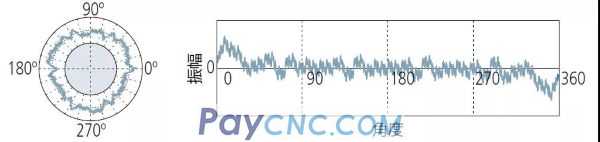
Influence of filter on measurement results
Because of the influence of various environments or other factors, in order to eliminate the noise, it is necessary to set the filter cut-off value when measuring the roundness. The following figure shows the influence of the filter on the measurement results.
So what information can we read out of the roundness measurement results?
Analysis of measurement charts
1UPR component (1 mountain/turn)
1 The UPR component represents the eccentricity of the workpiece relative to the rotation axis of the measuring instrument. The amplitude of the waveform depends on its level adjustment.
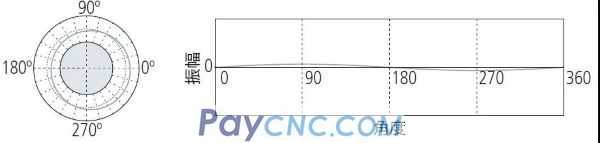
2UPR component (2 hills/turn)
The 2UPR component may indicate:
① The level adjustment of the measuring instrument is insufficient;
② Circular runout caused by incorrect installation of the workpiece on the machine tool that formed its shape;
③ The shape of the workpiece is elliptical in design, such as in IC engine pistons.
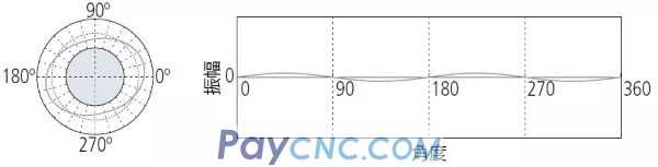
3~5UPR component (mountain/turn)
May mean:
① Deformation caused by too tight holding chuck on the measuring instrument.
②When unloading from the fixed chuck of the processing machine tool, the slack deformation caused by stress release.
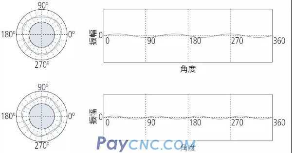
5~15 UPR component (mountain/turn)
It usually indicates an unbalanced factor in the processing method or the process of producing the workpiece.
15 (more) UPR component (hill/turn)
15 (or more) UPR conditions are usually caused by tool chatter, machine vibration, coolant delivery effects, material inhomogeneity, etc.