USD
USD
Several important cutting parameters of CNC milling
Some time ago, in order to improve the processing efficiency, a master directly raised the speed S in the program by a lot; I heard it and thought it over. This master might increase the cost of the tool. (Why? I will talk about it below.)
Regarding the improvement of workshop production efficiency, it actually consists of two parts:
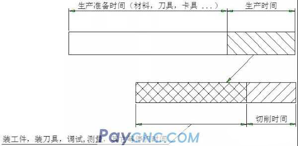
Production preparation
Production time
Production preparation accounts for the most production time, especially for small-batch and multi-variety processing and production (such as the preparation and turnover of materials, tools, fixtures, etc.). This is mainly at the management level, and the test is the workshop management ability!
Production time is divided into two situations:
Downtime waiting time
Cutting time
Downtime waiting time, such as loading and unloading workpieces, changing clamping tools, etc., is also time-consuming. The cutting time, which is the program running time, only takes up a small part of the production time, as shown in the following figure:
Well, production management is the core of efficiency improvement. This is a matter of management. As our ordinary employees, how to use the tools well and how to give reasonable cutting parameters is what we care about!
In today’s article, I will use a picture to introduce you to several important milling parameters in terms of cutting parameters:
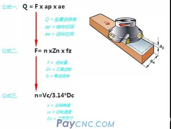
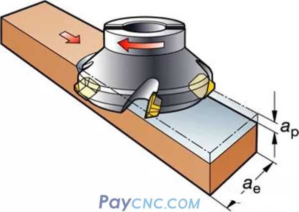
The first formula is: metal removal rate formula (Q = F x ap x ae)
The metal removal rate is proportional to F, ap, and ae, that is, increasing one of these three parameters can increase the metal removal rate.
This is why increasing the speed in the program does not directly increase the processing efficiency.
(This refers to the inability to directly improve processing efficiency)
Improve the processing efficiency by improving the cutting parameters. As mentioned earlier, the cutting time only takes up a small part of the overall production efficiency. Therefore, I will focus on simply and rudely increasing the cutting parameters, which may increase the tool cost in the workshop and affect the quality of the parts. Wait.
For example, the feed rate F in the program is very easy to adjust. If the feed rate F is increased, the metal removal rate will increase. With such a small change, what impact might it have on the tool and parts?
See the second formula specifically: the feed formula (F= n xZn x fz)
Assuming that the other two parameters remain unchanged:
1. If n becomes larger, that is, you increase the speed S in the program. This effect is obvious. If n becomes larger, the linear velocity Vc needs to become larger (the relationship between Vc and n depends on the third formula: n=Vc/3.14*Dc).
The line speed will increase, and the line speed has the most direct relationship with the tool life.
Tool industry: Do a lot of the impact of cutting depth ap, feed F and linear velocity Vc on tool life.
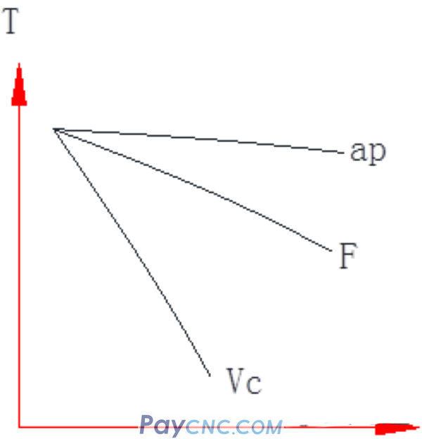
As shown in the figure above: the horizontal axis represents tool wear, and the vertical axis T represents tool life.
among them:
1. The depth of cut Ap increased by 50%, blade wear increased by 20%;
2. The amount of feed F increased by 20%, and blade wear increased by 20%;
3. Cutting speed increased by 20%, blade wear increased by 50%;
That is, as the cutting speed increases, the tool life will be shortened sharply. Therefore, when the tool life is too short or the tool wears very fast during the cutting process, the cutting speed can be reduced, which is reflected in the program, and the speed S in the program can be reduced;
2. Z becomes larger, which means the number of teeth increases. In this way, milling parts in a narrow space may cause chip removal problems. At the same time, if more blades mesh with the workpiece at the same time, the cutting force will increase, which means that during the cutting process The tendency of vibration will increase.
Vibration during processing can be solved by reducing the number of tool teeth. Of course, vibration is related to many factors, such as the number of teeth of the tool, the entering angle of the tool, the overhanging depth of the tool, part clamping, programming, machine tool, etc. Due to space reasons, I will explain the causal relationship and the corresponding solutions later in a circular diagram.
3. The fz becomes larger, that is to say, the feed per tooth is larger, and the feed per tooth is larger, and the most direct effect is that the cutting force becomes larger.
The cutting force becomes larger, so the requirement on the cutting edge strength of the tool also becomes higher, such as the following figure, the cutting edge:
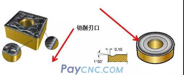
So, during the cutting process, if the blade is easy to jump
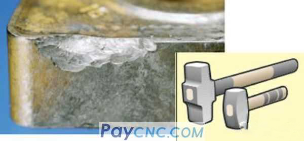
There are many forms of blade wear, and the blade is just one of them. I will share the countermeasures for various forms of blade wear in a small range of WeChat Moments. For the 8 common forms of wear, I used tens of thousands of words to analyze the principles and give the corresponding solutions. )
If the blade is prone to snapping, choose a softer blade (a higher grade, see my previous article on tool material classification for details). The blade is softer and resistant to impact, and naturally it is not easy to break.
Zou Jun, I have always shared programming dry goods, here I will give you a solution from a programming perspective.
Emphasize:
Milling is a cyclic process where the cutting edge of the tool enters the workpiece-----cut----exit the workpiece (except for axial feed, such as drilling and plunge milling).
There are usually two forms of toolpaths in this cycle:
Down milling
Up milling
Many masters who have been in contact with machining centers may know: down milling, up milling;
But what is the relationship between these two toolpaths and the knife edge?
In fact, the up-and-down milling is only a superficial phenomenon, behind which is the size of the tool's compressive stress and tensile stress.
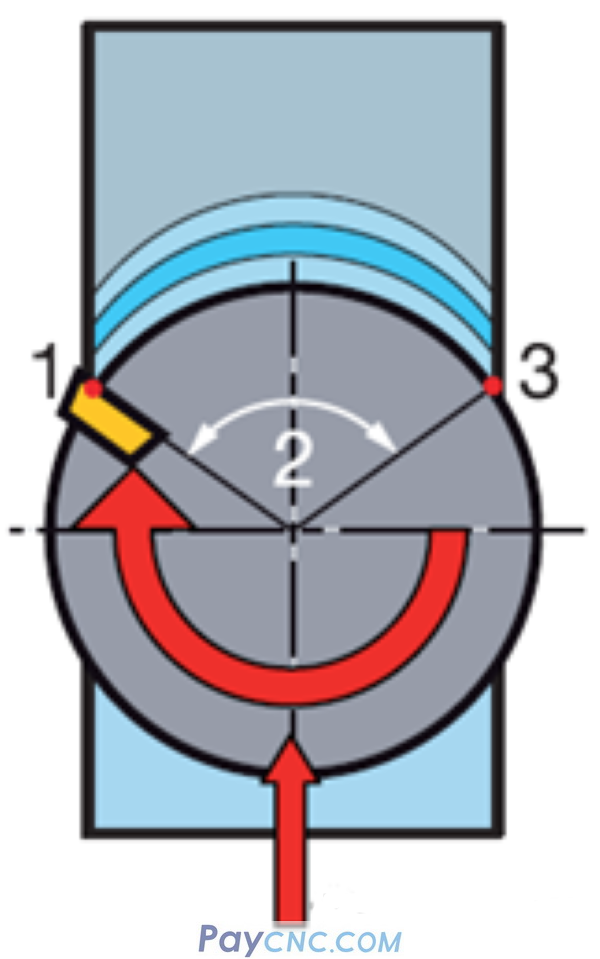
Come, look at the following two pictures to explain the force principle of the cutting edge of the tool:
This picture is down milling: when the tool cuts into the workpiece, the cutting thickness is the largest, and when it exits the workpiece, the cutting thickness is the smallest.
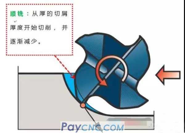
Then, with down milling, when the tool cuts into the workpiece, the thickness of the iron filings is the largest, and the impact force on the cutting edge of the tool is large (that is, a large pressure is given to the cutting edge); when the workpiece is exited, the chip thickness is the smallest. The tensile stress on the cutting edge of the tool is small because of the force and reaction force.
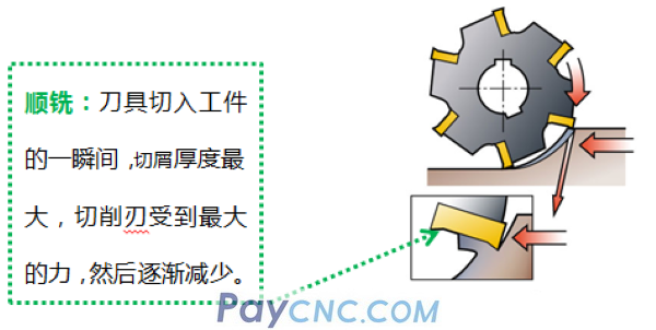
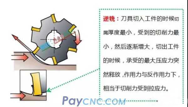
The following picture shows up-milling: when the tool cuts into the workpiece, the cutting thickness is the smallest, and when it exits the workpiece, the cutting thickness is the largest.
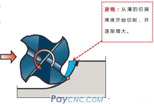
Then, with up-cut milling, the moment the tool cuts into the workpiece, the cutting thickness is the smallest, and the impact force on the tool is small; (that is, a small pressure is given to the cutting edge of the tool); the thickness of the iron filings is the largest when the workpiece is exited, then The maximum pressure on the tool is suddenly released. According to the force and reaction force, the cutting edge of the tool receives the greatest tensile stress.
As shown below:
Ok, I understand the force principle of the cutting edge of the tool during the milling process. In addition, how to judge down milling and up milling when programming?
I once said that everything is divided into two states, such as up and down, left and right, east and west, male and female... These two states derive a rich and colorful world, so no matter how complicated the part is, there are two forms according to the characteristics of the workpiece, either external (shape) or internal (shape), which constitute parts of various shapes.
Then for milling "shape"
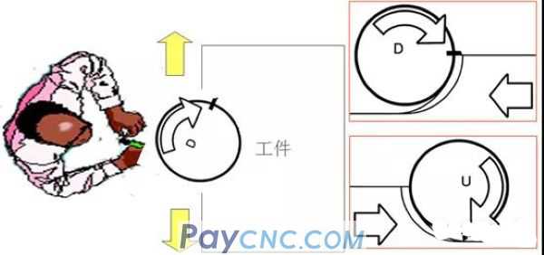
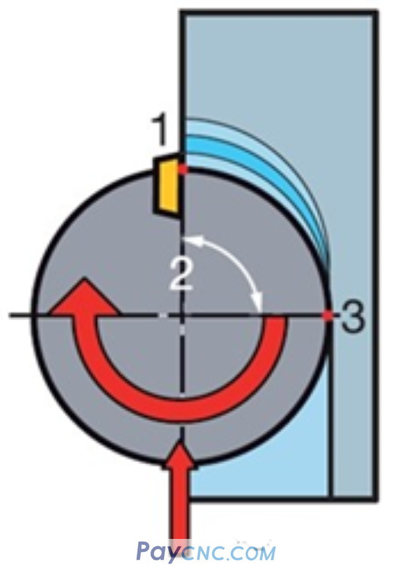
Clockwise feed is down milling, and counterclockwise feed is up-cut milling. (As shown below:)
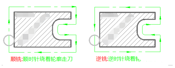
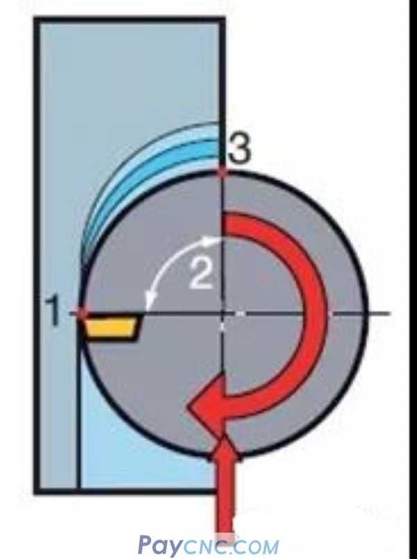
Then for milling "inner shape"
Clockwise feed is counter milling, and counterclockwise feed is down milling.
As shown below:
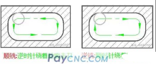
Well, look at the above picture carefully, it is very useful, remember, you will judge.
Well, first analyze the theories involved in down milling and up milling. What use are these theories in our actual programming?
For a simple example (as shown in the figure below), a plane is required to be milled.
Before writing this program, we first select the tool, there are often two choices:
1. The tool diameter is smaller than the part plane size
2. The tool diameter is larger than the part plane size
In the above two cases, I believe everyone will choose the tool diameter to be slightly larger than the part plane size, so that the processing efficiency is high.
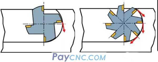
Then, if the tool diameter is larger than the part plane size, there are three cutting methods. Zou Jun, I will draw three tool path diagrams for you.
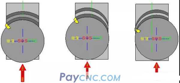
1. (As shown in the left picture) the tool center and the part center coincide, cutting into and out of the workpiece, the cutting thickness is always the same.
2. (As shown in the middle picture) the tool center is on the left side of the part center, the cutting thickness is the thickest when cutting into the workpiece, and the cutting thickness is the thinnest when cutting out the workpiece.
3. (As shown in the middle picture) the tool center is on the right side of the part center. When cutting into the workpiece, the cutting thickness is the thinnest, and the cutting thickness of the workpiece is the thickest.
Okay, repeat the important things (and you'd better watch it three times at the same time), through the above three toolpaths:
The first case: the tool center and the part center coincide, or it can be understood that the full cutting is used when milling the workpiece, and the cutting thickness of the tool cutting into and exiting the workpiece is the same.
The second case: the tool center is offset to the left side of the part center, or it can be understood as milling the outer contour of the workpiece (clockwise), as shown in the figure, that is, down milling is used. The cutting thickness is the thickest when the tool cuts into the workpiece. The cutting thickness of the workpiece is the thinnest.
The third case: the tool center is offset to the right side of the part center, or it can be understood as milling the outer contour of the workpiece (counterclockwise cutting), as shown in the figure below, that is, up-milling is used, and the cutting thickness is the thinnest when cutting into the workpiece. The cutting thickness of the workpiece is the thickest.
After the example is analyzed, (except axial feed and plunge milling), whether it is plane machining, contour, or cavity machining, the tool position relative to the part during programming is nothing more than the above three. (Again, although using face milling as an example, you can also regard it as milling contours, cavities, etc.)
Then, the first case is equivalent to full-cut cutting, for example, a slot is milled in the middle of a plate, for example, a solid workpiece is milled with a cavity, and the first tool is full-cut cutting. This kind of situation does not distinguish down milling. . (Of course, except for some programming strategies for high-speed milling, I will specifically talk about programming strategies for high-speed milling later).
In the other two cases, the up-down milling is determined by the tool position and the feed direction.
Then combined with the above explanation, how to use CW and CW milling when programming? I will focus on a simple analysis from the perspective of the tool.
There are many types of tools, and there are also different materials, such as high-speed steel, cemented carbide, ceramic, CBN, diamond, etc. Generally speaking, from the perspective of tool material, there are at least two important indicators: hardness and toughness.
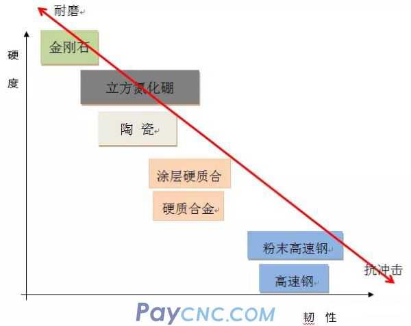
The horizontal axis represents toughness, (as shown in the figure above), the closer to the right, the better the toughness of the tool material, that is, the toughness of the high-speed steel tool is good, and the toughness of the diamond tool is poor.
The vertical axis represents the hardness, (as shown in the figure above), the higher the corresponding tool material hardness is, that is, the tool hardness of diamond material is high, and the tool hardness of high speed steel material is low.
Tools with good toughness are resistant to impact, but not wear-resistant; tools with high hardness are wear-resistant, but not lazy to impact.
Combining the up-and-down milling programming strategy with the two characteristics of tool toughness and hardness, they are divided into four types:
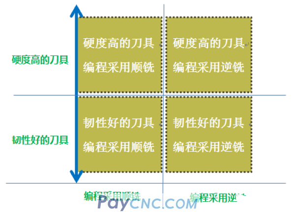
1. Tools with high hardness are programmed by down milling
2. High-hardness tool programming adopts up-milling
3. Tool with good toughness, down milling is used for programming
4. Tool with good toughness, up-milling is used for programming
When programming, which one would you choose?
For example, you are currently using a tool with higher hardness (such as cubic boron nitride CBN tool)
The recommended method is to use the first type: tool programming with high hardness uses down milling.
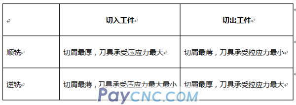
Down milling, cutting into the workpiece, although the cut chips are the thickest and the tool bears the greatest compressive stress, but due to the support of the tool body (positioning surface), the chips are the thinnest when the workpiece is cut out, and the tool bears the least tensile stress, so it is not easy to jump Cutting edge, tool life will be significantly improved.
Conversely, if the programming of a high-hardness tool uses up-milling, the chip is thickest when the workpiece is cut out, and the maximum compressive stress that the tool bears is suddenly released (according to the force and reaction force), the cutting edge of the tool receives the greatest tensile stress. The cutting edge is easily taken away by the iron filings, causing the cutting edge of the tool to fall off.
Okay, I made a simple analysis from the perspective of tool material. Of course, the up and down milling strategy can also be considered from other angles when programming, such as machining conditions, rough and fine machining, etc.
Take rough and fine machining as an example, Zou Jun, let me analyze briefly:
Back to the beginning of the article, the first formula mentioned: metal removal rate (Q = F x ap x ae)
Yes, rough machining is to improve the metal removal rate, so try to cut the depth and width as much as possible.
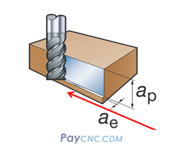
In the process of milling, the large depth of cut and width of cut means that the cutting edge of the tool is in contact with the workpiece. If down milling is used, the tool cuts into the workpiece and cuts the thickness, which will be subject to a greater impact (for the power of the machine, the parts There are also requirements for clamping rigidity, etc.) It is easy to cause vibration during the cutting process, and even the blade of the tool. On the contrary, up-milling is cutting thin in and thick out, which can solve the problems of large cutting depth in rough machining and easy to cause vibration.
Well, the up-and-down milling strategy in CNC programming can also be analyzed from multiple dimensions such as machine tools, fixtures, and workpiece materials, and will be explained slowly later.