USD
USD
Synchronous control and automatic tool setting
Realization of Synchronous Control and Automatic Tool Setting in CNC System
In the process of workpiece processing, auxiliary time such as tool adjustment and workpiece loading and unloading account for a considerable proportion of the processing cycle. Therefore, reducing the auxiliary time is essential to improve the processing efficiency.
In recent years, due to the continuous increase in labor costs, companies have encountered difficulties in recruiting workers, especially in the machinery manufacturing industry. This forces companies to update and transform equipment, increase automation, and reduce costs. Therefore, the automatic tool setting function shows great advantages. In addition, general equipment clamping can only process one part at a time. If multiple parts can be processed at a time, the efficiency can be doubled and the cost can be reduced.
This article will introduce the method of adding synchronous control and automatic tool setting functions and embedding the operation interface to the CNC system to simplify operation and improve efficiency.
Control principle
ASynchronization control
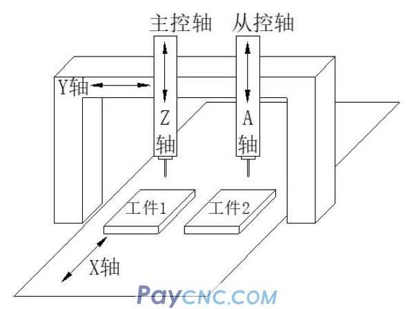
On some machine tools, as shown in Figure 1, the double vertical axis (Z and A two vertical axes) gantry engraving and milling machine tools, through the external control signal to switch the synchronization control on and off. When the synchronous control is started, the Z and A feed axes can be driven synchronously by commanding only one of the vertical axes.
The axis that becomes the standard for synchronous control is the master axis, and the axis that moves synchronously with the master axis is the slave axis. In order to achieve mechanical synchronization, it is also necessary to adjust the synchronization adjustment of the servo drive units of the master axis and the slave axis in the synchronization control.
The operation in which the synchronous control is started and the slave axis is moved in synchronization with the main control axis is called synchronous operation; while the operation in which the synchronous control is turned off and the main control axis and the slave axis move independently is called normal operation [1].
BAutomatic tool setting
Automatic tool setting is a method in which the tool moves to touch the tool setting instrument by executing the special program for tool setting and the G31 program jump instruction in the numerical control system to obtain relevant data such as tool length, radius, and wear.
Among them, the tool setting instrument is the key equipment to realize the automatic tool setting function. The response speed and repeat response accuracy of the tool setter will directly affect the measurement accuracy. Before the automatic tool setting function is used, the position coordinates of the tool setting instrument on the worktable should be calibrated, and the calibrated recoil should be stored in the variables of the numerical control system to provide a benchmark for the next use.
Specify axis movement after G31 command, and linear interpolation can be performed like G01. If an external jump signal (ie, tool setting instrument action trigger signal) SKIP is input during the execution of the G31 instruction, the execution of this instruction will be interrupted and the next block will be executed. When the CNC system receives the jump signal, the coordinate value of each axis is stored in the special variables #5016~#5019[2].
CSynchronous control and tool setting operation interface
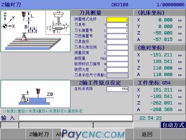
In order to facilitate the use of the operator, the interface and operation are added to the GSK208D engraving and milling CNC system, as shown in Figure 2:
Interface parameter description:
Measurement mode selection: 1: Length 2: Diameter 3: Length & Diameter
4: Length calibration 5: Diameter calibration;
Tool number: the tool number currently to be measured;
Tool length offset number: store the offset number of the current tool length (the default is the same as T);
Tool radius offset number: store the offset number of the current tool diameter (the default is the same as T);
Tool diameter: measured tool diameter (+s: right-handed tool -s: left-handed tool);
Tool length estimation: the measured tool length (please enter the exact value when calibrating);
Measuring depth: the incremental depth from the starting position to the measuring position;
Overtravel amount: overtravel amount and radial safety clearance value;
Damaged tool offset number: a free tool offset number is used as the location of tool damage identification;
Damage tolerance: the damage detection tolerance set by the program;
Tool radius size adjustment: the cutting state of the tool size adjustment, (when the diameter is calibrated, it is the probe diameter);
Coordinate system selection: selection range: G54~G59, P1~P50 (G54)
Key Description:
[Z axis tool setting]: Select the tool setting axis as Z axis;
[A-axis tool setting]: Select the tool setting axis as A-axis;
[Sync Start]/[Sync Cancel]: Start or cancel the synchronization control function;
[Start]: Start the measurement program of the tool on the Z axis/A axis.
Realization of synchronous control and automatic tool setting
This includes the realization of two functions: synchronous control function and automatic tool setting function.
ARealization of synchronization control function
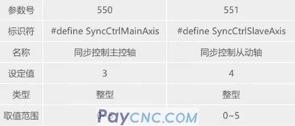
Synchronous control function parameter definition and setting
In order to meet the synchronous control of different mechanical structures, some parameters about synchronous control need to be defined, as shown in Table 1:
Synchronous control function command code, signal and control logic
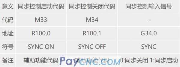
In order to meet the free switching between start and close of synchronous control, it is necessary to define synchronous control start code M33, close code M34 and synchronous control input signal SYNC, as shown in Table 2:
The following figure 3 shows a schematic ladder diagram for the realization of synchronization control:

Synchronous control operation
In order to realize the convenient operation of synchronous control, in addition to embedding the development operation interface and buttons in the CNC system, it is also necessary to write subroutines for synchronously starting and canceling button operation calls, as shown in Table 3 below:
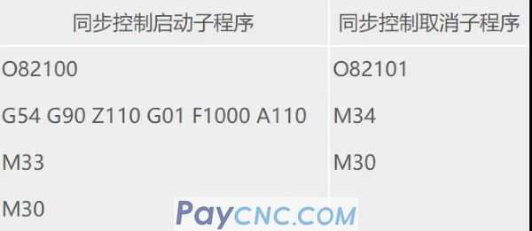
Steps:
Switch to automatic operation mode and switch the interface to the tool setting interface;
Select [Synchronize Start]/[Synchronize Cancel] button, after selection, subroutine O82100/O82101 will be called;
Press the cycle start button on the operation panel to execute.
BRealization of automatic tool setting
Instruction code format: G31 G90/G91 X_ Y_ Z_ F_
X_Y_Z_: the end point coordinates of each axis;
F: The feed speed (mm/min) when moving to the end point coordinate.
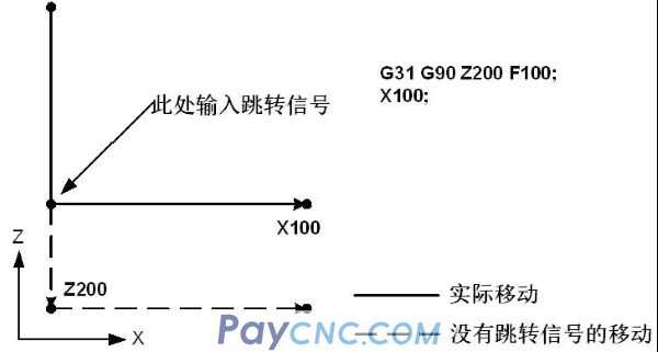
Function: After the G31 code, linear interpolation can be commanded just like G01. During the execution of this code, if an external jump signal is input, the execution of the code will be interrupted and the next block will be executed. When not programming the machining end point, but using the signal from the machine tool to specify the machining end point, use the skip function. For example for grinding. The jump function is also used to measure the size of the workpiece. [3]
Note: G31 is a non-modal G code, which is only valid in the specified block.
Example: The next block of G31 is a single-axis movement of absolute value command, as shown in Figure 4:
Note: It can be set by parameter No.4#7 (skip signal SKIP, when (0: is 1, 1: is 0) as signal time).
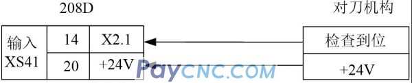
Automatic tool setting I/0 connection
Since the signal used for tool measurement here is the G31 jump signal X2.1, it is required that the measurement arrival signal in both the Z-axis direction and the A-axis direction should be detected by X2.1. The signal connection is shown in Figure 5:
Automatic tool setting operation steps
Switch to automatic control mode and confirm whether the synchronization control is cancelled. If the synchronization control has been cancelled, skip step 2 and operate step 3 directly;
Select [Sync Cancel] button, and press Cycle Start to execute synchronization cancel;
Select [Z-axis tool calibration] or [A-axis tool calibration] and set related measurement parameters in the interface;
Press the interface [Start] button, and the system will automatically call No. O82000 tool setting macro program;
Press the cycle start button on the operation panel to execute the tool setting macro program.
Repeat step 3 for the other axis to perform tool setting.
After the tool setting of the Z axis and the A axis is completed, select the [Synchronous Start] button and press Cycle Start to execute the synchronous start.
Select the workpiece processing program and execute the simultaneous processing of dual workpieces.
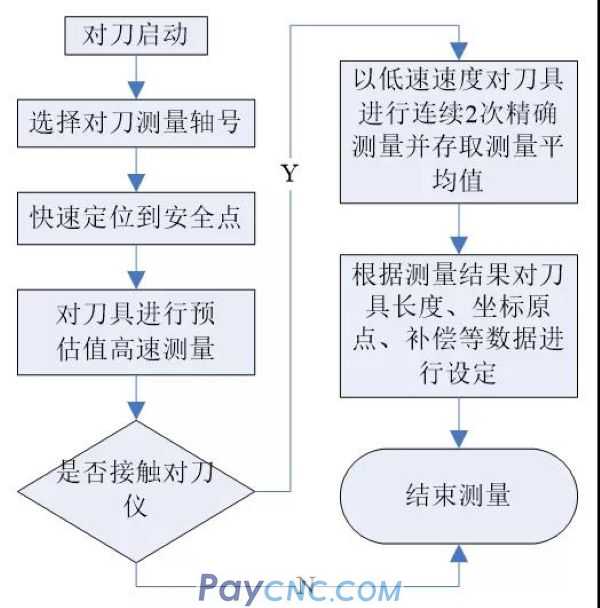
Automatic tool setting program
Write the macro program according to the control flow chart shown in Figure 6, and set the tool setting macro program number to O82000.
in conclusion
According to the comparison of the actual processing results of users, it is found that when the synchronous control and automatic tool setting functions are used, the operation is simple, convenient, and easy to learn; the processing efficiency is more than doubled, and the overall cost is reduced. With the advancement of technology and the intensification of competition, the selection of Jinggong machinery and equipment will become more and more advanced, the level of automation will become higher and higher, its product structure will continue to be adjusted, the market capacity will continue to expand, multi-station processing and automatic tool setting Applications will become more and more popular.
In the process of workpiece processing, auxiliary time such as tool adjustment and workpiece loading and unloading account for a considerable proportion of the processing cycle. Therefore, reducing the auxiliary time is essential to improve the processing efficiency.
In recent years, due to the continuous increase in labor costs, companies have encountered difficulties in recruiting workers, especially in the machinery manufacturing industry. This forces companies to update and transform equipment, increase automation, and reduce costs. Therefore, the automatic tool setting function shows great advantages. In addition, general equipment clamping can only process one part at a time. If multiple parts can be processed at a time, the efficiency can be doubled and the cost can be reduced.
This article will introduce the method of adding synchronous control and automatic tool setting functions and embedding the operation interface to the CNC system to simplify operation and improve efficiency.
Control principle
ASynchronization control
On some machine tools, as shown in Figure 1, the double vertical axis (Z and A two vertical axes) gantry engraving and milling machine tools, through the external control signal to switch the synchronization control on and off. When the synchronous control is started, the Z and A feed axes can be driven synchronously by commanding only one of the vertical axes.
The axis that becomes the standard for synchronous control is the master axis, and the axis that moves synchronously with the master axis is the slave axis. In order to achieve mechanical synchronization, it is also necessary to adjust the synchronization adjustment of the servo drive units of the master axis and the slave axis in the synchronization control.
The operation in which the synchronous control is started and the slave axis is moved in synchronization with the main control axis is called synchronous operation; while the operation in which the synchronous control is turned off and the main control axis and the slave axis move independently is called normal operation [1].
BAutomatic tool setting
Automatic tool setting is a method in which the tool moves to touch the tool setting instrument by executing the special program for tool setting and the G31 program jump instruction in the numerical control system to obtain relevant data such as tool length, radius, and wear.
Among them, the tool setting instrument is the key equipment to realize the automatic tool setting function. The response speed and repeat response accuracy of the tool setter will directly affect the measurement accuracy. Before the automatic tool setting function is used, the position coordinates of the tool setting instrument on the worktable should be calibrated, and the calibrated recoil should be stored in the variables of the numerical control system to provide a benchmark for the next use.
Specify axis movement after G31 command, and linear interpolation can be performed like G01. If an external jump signal (ie, tool setting instrument action trigger signal) SKIP
CSynchronous control and tool setting operation interface
In order to facilitate the use of the operator, the interface and operation are added to the GSK208D engraving and milling CNC system, as shown in Figure 2:
Interface parameter description:
Measurement mode selection: 1: Length 2: Diameter 3: Length & Diameter
4: Length calibration 5: Diameter calibration;
Tool number: the tool number currently to be measured;
Tool length offset number: store the offset number of the current tool length (the default is the same as T);
Tool radius offset number: store the offset number of the current tool diameter (the default is the same as T);
Tool diameter: measured tool diameter (+s: right-handed tool -s: left-handed tool);
Tool length estimation: the measured tool length (please enter the exact value when calibrating);
Measuring depth: the incremental depth from the starting position to the measuring position;
Overtravel amount: overtravel amount and radial safety clearance value;
Damaged tool offset number: a free tool offset number is used as the location of tool damage identification;
Damage tolerance: the damage detection tolerance set by the program;
Tool radius size adjustment: the cutting state of the tool size adjustment, (when the diameter is calibrated, it is the probe diameter);
Coordinate system selection: selection range: G54~G59, P1~P50 (G54)
Key Description:
[Z axis tool setting]: Select the tool setting axis as Z axis;
[A-axis tool setting]: Select the tool setting axis as A-axis;
[Sync Start]/[Sync Cancel]: Start or cancel the synchronization control function;
[Start]: Start the measurement program of the tool on the Z axis/A axis.
Realization of synchronous control and automatic tool setting
This includes the realization of two functions: synchronous control function and automatic tool setting function.
ARealization of synchronization control function
Synchronous control function parameter definition and setting
In order to meet the synchronous control of different mechanical structures, some parameters about synchronous control need to be defined, as shown in Table 1:
Synchronous control function command code, signal and control logic
In order to meet the free switching between start and close of synchronous control, it is necessary to define synchronous control start code M33, close code M34 and synchronous control input signal SYNC, as shown in Table 2:
The following figure 3 shows a schematic ladder diagram for the realization of synchronization control:
Synchronous control operation
In order to realize the convenient operation of synchronous control, in addition to embedding the development operation interface and buttons in the CNC system, it is also necessary to write subroutines for synchronously starting and canceling button operation calls, as shown in Table 3 below:
Steps:
Switch to automatic operation mode and switch the interface to the tool setting interface;
Select [Synchronize Start]/[Synchronize Cancel] button, after selection, subroutine O82100/O82101 will be called;
Press the cycle start button on the operation panel to execute.
BRealization of automatic tool setting
Instruction code format: G31 G90/G91 X_ Y_ Z_ F_
X_Y_Z_: the end point coordinates of each axis;
F: The feed speed (mm/min) when moving to the end point coordinate.
Function: After the G31 code, linear interpolation can be commanded just like G01. During the execution of this code, if an external jump signal is input, the execution of the code will be interrupted and the next block will be executed. When not programming the machining end point, but using the signal from the machine tool to specify the machining end point, use the skip function. For example for grinding. The jump function is also used to measure the size of the workpiece. [3]
Note: G31 is a non-modal G code, which is only valid in the specified block.
Example: The next block of G31 is a single-axis movement of absolute value command, as shown in Figure 4:
Note: It can be set by parameter No.4#7 (skip signal SKIP, when (0: is 1, 1: is 0) as signal time).
Automatic tool setting I/0 connection
Since the signal used for tool measurement here is the G31 jump signal X2.1, it is required that the measurement arrival signal in both the Z-axis direction and the A-axis direction should be detected by X2.1. The signal connection is shown in Figure 5:
Automatic tool setting operation steps
Switch to automatic control mode and confirm whether the synchronization control is cancelled. If the synchronization control has been cancelled, skip step 2 and operate step 3 directly;
Select [Sync Cancel] button, and press Cycle Start to execute synchronization cancel;
Select [Z-axis tool calibration] or [A-axis tool calibration] and set related measurement parameters in the interface;
Press the interface [Start] button, and the system will automatically call No. O82000 tool setting macro program;
Press the cycle start button on the operation panel to execute the tool setting macro program.
Repeat step 3 for the other axis to perform tool setting.
After the tool setting of the Z axis and the A axis is completed, select the [Synchronous Start] button and press Cycle Start to execute the synchronous start.
Select the workpiece processing program and execute the simultaneous processing of dual workpieces.
Automatic tool setting program
Write the macro program according to the control flow chart shown in Figure 6, and set the tool setting macro program number to O82000.
in conclusion
According to the comparison of the actual processing results of users, it is found that when the synchronous control and automatic tool setting functions are used, the operation is simple, convenient, and easy to learn; the processing efficiency is more than doubled, and the overall cost is reduced. With the advancement of technology and the intensification of competition, the selection of Jinggong machinery and equipment will become more and more advanced, the level of automation will become higher and higher, its product structure will continue to be adjusted, the market capacity will continue to expand, multi-station processing and automatic tool setting Applications will become more and more popular.